23
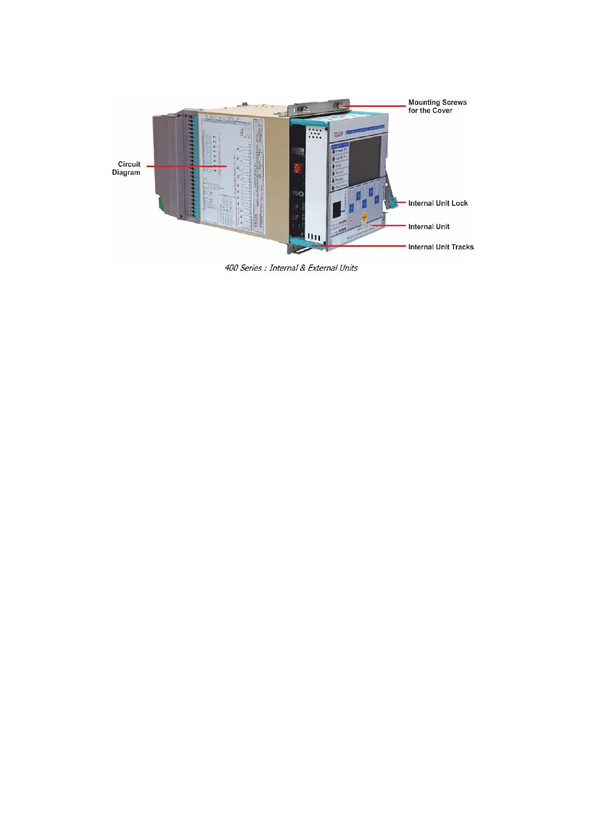
Image 3.3 Internal & External Units
3.19 Circuit Diagram
The circuit diagram of the device is fixed on the relay case. Users do not need to keep
documents for basic cabling duties on the field thanks to this inerasable diagram.
3.20 Internal Unit
The internal unit houses the entire electronic systems, making it possible to replace the whole
unit within seconds without having to black out the system. The modular design of electronic
systems provides rapid and affordable maintenance & reparation in need. Critical electronic
components are screened from noises in the Faraday cage inside of the unit.
3.21 Mounting Screws for the Cover
Mounting screws are fixed on the case and are employed to mount the cover on the case.
3.22 Internal Unit Tracks
High-endurance internal unit tracks provide robust draw-in and draw-out operation of the
internal unit.