4.10 Trolley
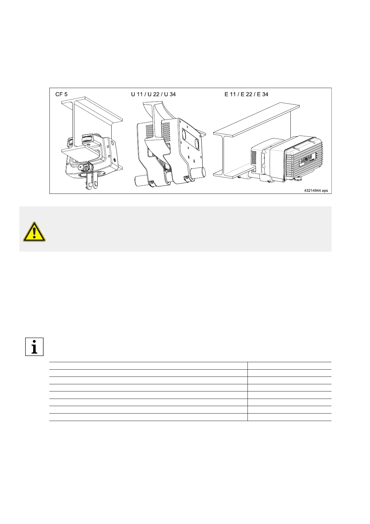
Fig. 16
WARNING
Overload
There is danger to life and limb due to a possible excessive load of the trolley.
The load capacity of Demag chain hoists must not exceed the load capacity of the trolley.
I beam track
The use of I beams with parallel or sloping flanges according to DIN 1025 as tracks is possible.
The curve radii should be as large as possible in order to ensure good travel characteristics.
I beam tracks should be bent with the utmost care in order to obtain a clean, regular curve.
Hoist travel on I beam tracks must in no way be obstructed by protruding suspension bolts, screw heads, clamping
plates, joint flanges, etc.
Resilient buffers should be mounted at travel wheel axle level at the ends of tracks in order to prevent the trolley
from derailing (e.g. Demag clamp-fitted buffers).
For further information on the trolleys and the power supply, see following table.
Designation Part no.:
CF 5 trolley 203 568 44
U 11 / U 22 / U 34 trolley 203 569 44
E 11 / E 22 / E 34 travel drive 214 810 44
E 11 / E 22 / E 34 travel drive (circuit diagrams) 203 698 44
KBK 0 + 25 trailing cable power supply 202 487 44
KBK 0 + 25 power supply lines 202 386 44
Clamp-fitted buffers 203 313 44
Tab. 24
Curve radii for trolleys
The specified curve radii apply for normal applications. Contact the manufacturer or his representative for frequent
curve travel operation (e.g. automatic installations).
36
21480244/181209