Do you have a question about the DEMAG DC-Com 5 and is the answer not in the manual?
Identifies potential dangers and risks associated with operation.
Details the function and location of the emergency stop.
Essential safety for initial commissioning.
Mandatory safety rules for operating the hoist.
Procedure for using and understanding the emergency stop.
Critical safety guidelines for all maintenance tasks.
Comprehensive table of required checks and intervals.
Safety guidelines for fault handling.
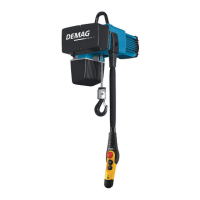
| Type | Electric Chain Hoist |
|---|---|
| Load Capacity | 500 kg |
| Safe Working Load | 500 kg |
| Control Type | Pendant control |
| Protection Class | IP55 |
| Chain Falls | 1 |
| Frequency | 50 Hz |
| Power Supply | 400 V / 50 Hz |
| Motor | Three-phase motor |
| Control | 24 V low voltage control |
| Chain Diameter | 5 mm |