9.2 7-segment display
The 7-segment display is located on the bottom side of the chain hoist behind a window.
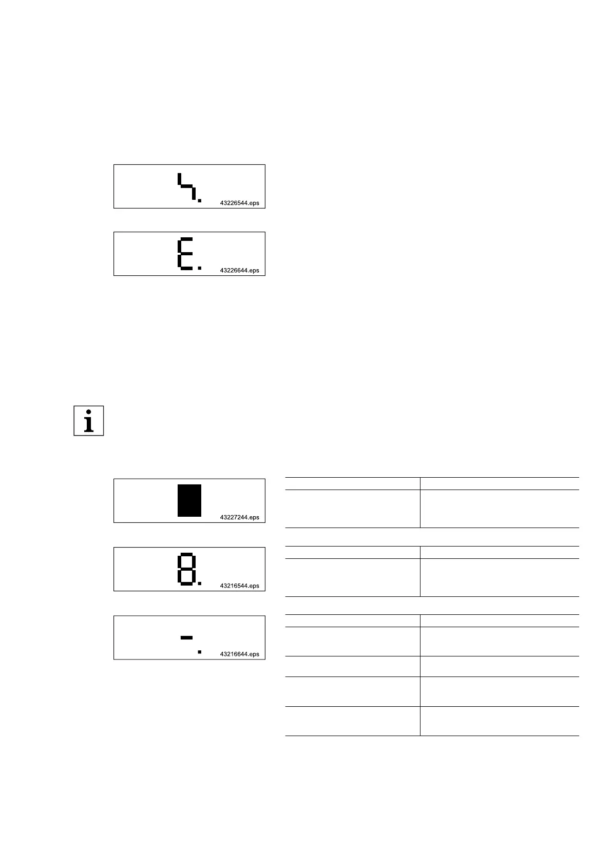
Fig. 71
Warning messages
Warning messages start with the lightning symbol.
Movement in the opposite direction is possible, the warning message
does not have to be acknowledged by means of the emergency stop.
Fig. 72
Error messages
Error messages start with an Error.
Before a new movement can be started, the error message must be ac‐
knowledged by means of the emergency stop.
Failed safety functions
If a safety function has failed, operation may only be continued after repair.
Malfunctions
The chain hoist can only function when it is correctly connected to the power supply. In the event of a malfunction,
therefore first check cables, strain relief and power supply connections. Malfunctions may also be caused by incorrect
transmission of commands from the control pendant. Therefore, check the control pendant and the control cable for
damage and the plug-in connector on the pendant and in the service enclosure for correct fit.
The symbols are shown one after the other.
● Please contact our after-sales service if the cause of the fault cannot be eliminated with the given measures.
9.3 General messages
Fig. 73 No lifting, no lowering
Possible cause
Remarks
No power supply (display dark)
Check mains connection and fuse link; check
connection cable for interruption; check mains
connector in the service enclosure. Check PE
phase for correct connection.
Tab. 69
Fig. 74 No lifting, no lowering
Possible cause
Remarks
Emergency stop actuated.
Emergency-stop cable interrupted.
Unlock emergency-stop switch by turning it.
Check dummy plug for trolley connection. Check
connections of the control cable on the pendant
and in the service enclosure.
Tab. 70
Fig. 75 Upper or lower end position is reached.
No lifting, no lowering
Possible cause
Remarks
Incorrect direction of motor rotation.
Two phases of the mains connection cable must
be changed. First disconnect unit from the power
supply.
Bimetal contact open.
Check motor connector X8 for continuity be‐
tween terminal 4 and 8.
When the voltage is switched on or the
emergency-stop is unlocked, a button is
already actuated.
Release button and actuate it again!
Control cable interrupted.
Check connections of the control cable on the
pendant and in the service enclosure. Check
control cable for continuity.
Tab. 71
21480244/181209
103