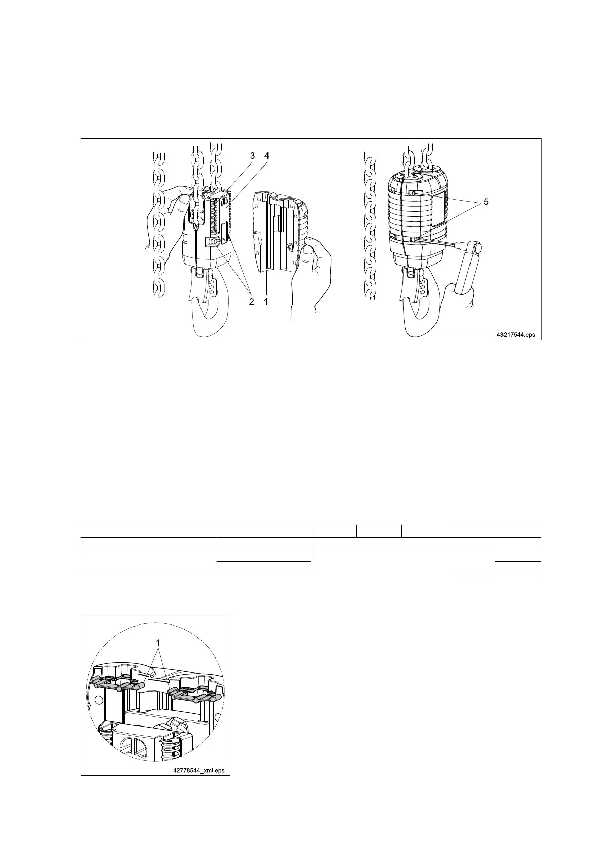
8.5.6.4 Replacing the (standard) bottom block with internal switch-off springs, reeving 2/1
Fig. 59
1. Remove the guide halves (1) (four M 6 screws);
2. Loosen the clamping screws (2) of the bottom block and remove the bottom block;
3. Introduce the chain into the new bottom block in the same position and orientation (chain must operate without
any twist);
4. Assemble the bottom block and tighten the screws (2) with 52 Nm;
5. Check the correct fit of the four switch-off springs (3) in the new bottom block halves (4);
6. Fit the new guide halves (1) and tighten the screws (5) with 5,5 Nm;
7. Apply load capacity plate;
8. Perform function check (run against operating limit switches and check 7-segment display).
Tightening torques [Nm] DC-Com 1 DC-Com 2 DC-Com 5 DC-Com 10
Reeving
1/1 1/1 2/1
Bottom block
with internal switch-off springs
Bottom block halves
- -
52,0
Guide halves 5,5
Tab. 60
Bottom block from approx. 09/2009
Fig. 60
From approx. 09/2009 the bottom block is provided with rubber lips (1) in
the area of the chain entry. During the annual inspection the rubber lip
must be checked for wear and correct fit.
90
21480244/181209