6
F - PROPER ADJUSTMENT OF STUFFING BOX
1. The liquid being pumped should constantly, yet slowly
drip from the stuffi ng box gland (17) when the pump
is running. This slow drip keeps the shaft from becoming
scored. NEVER tighten the gland so as to entirely stop
leakage through stuffi ng box. It increases the power and
wears the shaft in a short time.
2. The split gland (17) can be taken apart. This facilitates
repacking the stuffi ng box. Access to the packing (13) is
obtained by removing the nuts from bolts (209) which
fasten the stuffi ng box gland to the stuffi ng box head.
Clean out the drip holes in the gland occasionally as they
may become clogged, especially with new packing. The
drip hole allows the sealing liquid to drip thru the gland,
instead of passing between the gland and the shaft.
3. Standard pumps are equipped with a circulation tube
(127) from discharge to the stuffi ng box lantern ring so
that the pump will not suck air in along the shaft when
the pump is operating on a suction lift. If the pump is to
operate with positive suction head, disconnect this tube,
plug the holes concerned and run the pump with the
stuffi ng box gland as loose as possible to avoid
excessive shaft wear through the stuffi ng box.
G - GENERAL REPAIRS
If pumping any fl uid that could cause
bodily injury (Hot water, caustic, etc.),
Always use eye protection and wear
protective clothing over all exposed
body areas.
Whenever it is necessary to dismantle the pump for repairs,
it should be removed from the sub-base. Disconnect the
suction and discharge pipes and remove the four cap
screws holding pump to sub-base. Drain pump by removing
drain plug (216) in the bottom of the pump casing (1).
CLEAN AND INSPECT ALL PARTS
Extreme care should be exercised in keeping the parts
clean. Special precautions should be taken to keep ball
bearings dirt-free while in or out of the pump. The dirt will
damage the ball bearings, thus shortenting the trouble-free
service life of the pump.
Any part which is excessively worn or deteriorated should
be replaced with new parts from factory.
When ordering repairs refer to the illustrations for part
names and the pump name plate on which is stamped
the fi gure number, size and serial number. Without this
information we cannot identify the pump and parts in
question.
H - FOR INSPECTION AND REPAIR OF
LIQUID END
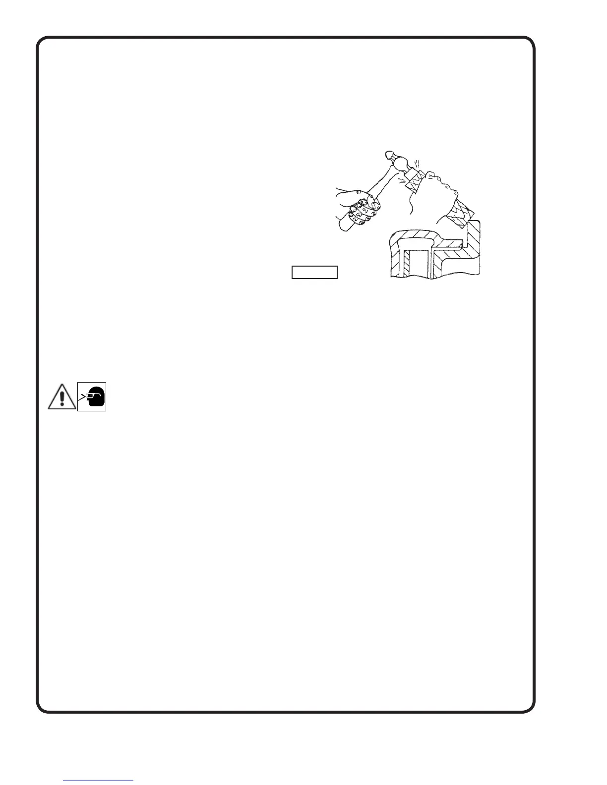
1. Remove suction head cap screws (215), then set a block
of wood against the fi nished fl ange or back of the frame
(19) and tap block lightly with a hammer to loosen
suction head. Remove suction head from pump and
place casing gasket (73) in a bucket of water to keep it
soft and pliable.
2. Bend and remove cotter pin (269) in castellated nut (24).
3. Unscrew the castellated nut (24) by turning
counter-clockwise while holding shaft (6) with a wrench
at drive coupling. Then slide impeller washer (270) off
the shaft.
4. To remove the impeller (2) from the shaft, make three
special cap screwsas follows:
Fig. 4001 - 3/8” x 16 NC with thread cut 1¾” long;
Fig. 4011 and 4021 - 1/2” x 13NC with thread cut 2” long.
Screw these cap screws into the three tapped holes in
the impeller shroud. The cap screws will tighten
against the stuffi ng box head (11) thus forcing the
impeller from the shaft. Lift key (32) from its seat in the
shaft .
5. To remove the pump casing (1), fi rst disconnect
by-pass tube (127) from the casing then remove casing
cap screws (215), casing and stuffi ng box gasket (241)
will lift off the frame (19). Place gasket in water.
6. The stuffi ng box head (11) can be removed after
loosening gland bolts (209) and nuts (210).
I - TO INSPECT OR REPLACE BALL
BEARINGS ON SHAFT
1. Dismantle liquid end of pump as described in section “H”
then loosen set screws in pump half of drive coupling
and remove coupling from pump shaft. Also remove key
(46) from shaft.
2. Unscrew bearing cover cap screws (213) remove
bearing cover (37) and gasket (303) and bearing
adjusting spring (347).Place gasket in water. Pull the
pump shaft (6) out thru the coupling end of the frame
(19). Slinger (40) will drop into support head drip basin.
Be careful not to lose it.
Figure 3