8
4. Apply a thin coating of clean light oil (not grease) to the
shaft and reposition seal head (52) on the support head.
Also apply a thin coating of light oil to the inside of the
seal bellows, slide the seal face carbon (D), bellows (G),
retainer (E), spring (F), spring holder (H) and spacer (61)
onto the shaft. NOTE: It may be necessary to use a
piece of tubing, slightly larger than the shaft, to push the
bellows and retainer onto the shaft. Apply pressure only
on the “tail section” of the bellows and retainer.
5. Insert casing cap screws (215) through holes in support
head and seal head and position gasket (73) on seal
head. Complete assembly of liquid end as described in
Section “K”.
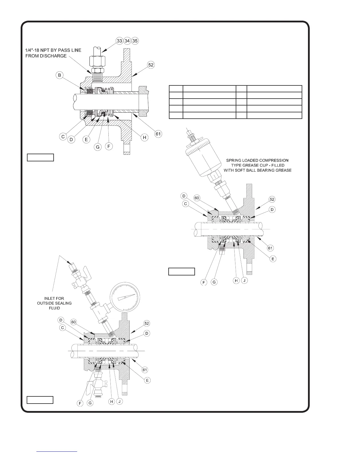
N - TO REPLACE DOUBLE MECHANICAL SEAL
Refer to Figures 5 & 6.
NOTE: Seals are available as a complete assembly only.
1. Special precautions must be observed when handling
a mechanical seal. DO NOT drop the seal face carbons
or fl oating seats nor scratch the lapped faces for these
pieces.
52 Seal Head F Seal Face Carbon
60 Seal Gasket G Retainer
C Seal Gland H Spring
D Seat Gasket J Bellows
E Floating Seat
2. To remove the seal assembly, dismantle the liquid end of
the pump as described in Section “H”, then unscrew
gland bolts (209) and nuts (210). Remove seal head
casting (52) from the support head, exposing the seal
assembly. Grasp the seal fi rmly by hand and twist it
on the shaft to break the seal between the bellows and
the shaft. The seal can now be pulled from the shaft.
Also remove the seal gland (56) from the shaft. Place
gland gasket (60) in water. Press seat gaskets (D) and
fl oating seat (E) from the seal gland (56) and seal head
(52).
3. To install new seal assembly, oil the outer surface of
seat gasket (D) and press seat gasket and fl oating seat
assembly (D) and (E) into the seal gland cavity. Also
apply oil to the outer surface of seat gasket and press
seat gasket and fl oating seat assembly into the cavity in
the base of the seal head (52). DO NOT SCRATCH
Figure 5
Figure 6
Figure 4