11
j. Pull off bearing housings (31) and (33) and bearings
(16) and (18). Note: On oil lubricated pumps shaft
collar (68) will also be removed.
k. Remove bearings from bearing housings.
l. Remove deÀ ectors (40) and casing wearing rings (7).
m. Remove packing (13) and lantern rings (29) or seal
gland (251), gasket (259) and mechanical seal (65).
n. Mark impeller location in relation to pump shaft and
remove by unscrewing shaft sleeves (one right
hand and one left hand thread).
o. If impeller wearing rings are to be replaced remove
all twelve set screws (296) and chisel ring (8) from
impeller (2).
5. REASSEMBLY
The following procedure is for the complete assembly of
the pump. This procedure must be followed for satisfactory
operation. If pump is not completely disassembled, use
only the steps that are applicable.
1. Press impeller wearing rings (8) onto impeller (2)
making sure they are evenly and fully seated.
(Impeller wearing rings are standard on pumps with
8” or larger discharge and optional on smaller units.)
2. Position impeller key (32) on pump shaft (6).
3. Slide impeller onto shaft. Center between shaft
threads.
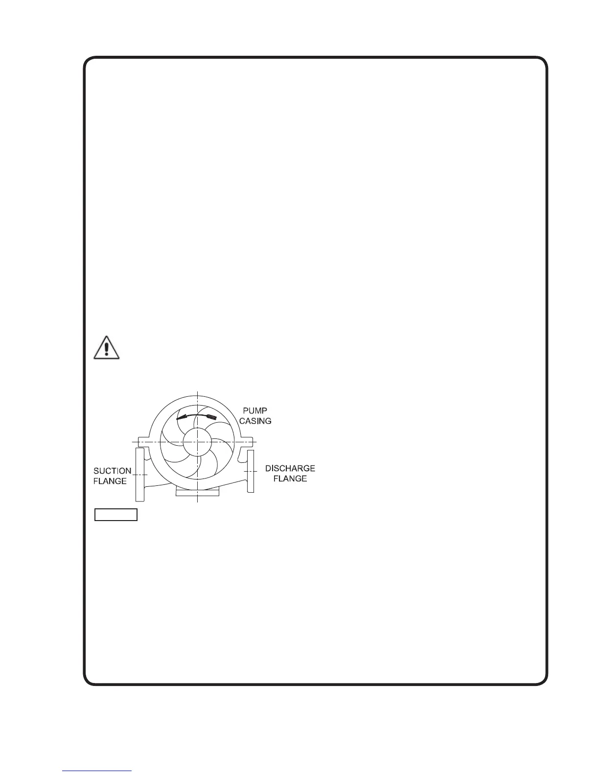
IMPORTANT! - When placed in casing, the
rotational curve of the impeller blades in
relation to the position of the pump discharge
must be as shown in Figure 6.
4. Slide shaft sleeve gasket (38) over shaft and place
one gasket against each side of the impeller.
5. Thread shaft sleeves (14) and (20) onto shaft,
one right and one left hand thread, but do not draw
up to impeller nut.
6. Place lantern rings (29), or seals (65), seal gaskets
(259) and seal glands (251), on the shaft along with
deÀ ectors (40).
7. Press lip seals (47) into bearing housings (31) and
(33) with the retaining spring toward the bearings.
Lip seal must be continually lubricated both during
and after assembly.
8. Slide bearings (16) and (18) into bearing housings
(31) and (33). Press only on the outer bearing race
if required.
9. Place bearing assemblies onto shaft. Press only on
the inner bearing race if required.
10. On grease lubricated pumps, place the lock washer
(69) on the shaft and secure the thrust bearing in
place with a lock nut (22).
For oil lubricated pumps, lock the thrust bearing
in place with two nuts (22). Lock nuts must be
installed so that a groove is created between them.
Press a shaft collar (68) onto shaft and against
the inboard bearing. Place an oil ring (60) in the
groove between the two lock nuts and shaft collar.
11. Press bearing dust cover (123) into bearing cover
(37). Then place gaskets (303), (use only on oil
lubricated pumps) and bearing covers (35) and (37)
on bearing housings and secure with cap screws
(245).
NOTE: On grease lubricated pumps, the grease
¿ tting (207) must match the dowel pin hole in the
bearing housing.
On oil lubricated pumps, the air vent (235) must
match the dowel pin hole in the bearing housing.
12. Position casing wearing rings (7) on the rotating
element and lower the complete assembly into the
lower casing. The tongue on the casing ring must
match the slot in the lower casing.
13. Match bearing caps (41) and (43) to marks on the
casing and position on dowel pins (247) which
extend from the bearing housings. Fasten securely
with cap screws (239).
14. Position impeller in the center of the casing and
tighten both shaft sleeves against the impeller.
15. Position the casing gasket on the lower casing.
NOTE: On pumps with mechanical seals, allow
the gasket to overhand the casing where the
seal gland gasket (259) mates. Trim the excess
prior to tightening the seal gland.
Inspect inside of both casing halves and remove
all foreign objects. Then carefully lower upper
casing (1B) onto dowel pin (246).
16. Place swing bolts (209) in proper positions and
secure the two casing halves together with nuts
(213) and cap screws (215).
For pumps using ring type packing:
Place packing rings (13) over the pump shaft and
slide into stuf¿ ng box. Alternate position of ring
splices 120° apart. Position lantern ring so that seal
water passage is in line with the lantern ring.
When packing is complete, place split gland (17),
gland clips (206), and nuts (210) on swing bolts.
Draw nuts down tight to seat bottom rings of
packing, then loosen nuts to ¿ nger tight for starting.
For pumps using mechanical seal:
Place nuts on swing bolts and tighten. Attach piping
for seal water if used.
17. Be sure all pipe plugs are in place and rotating
element turns freely.
Figure 6
 Loading...