6
WARNING - Coupling guards must be used to
avoid serious injury to operating personnel.
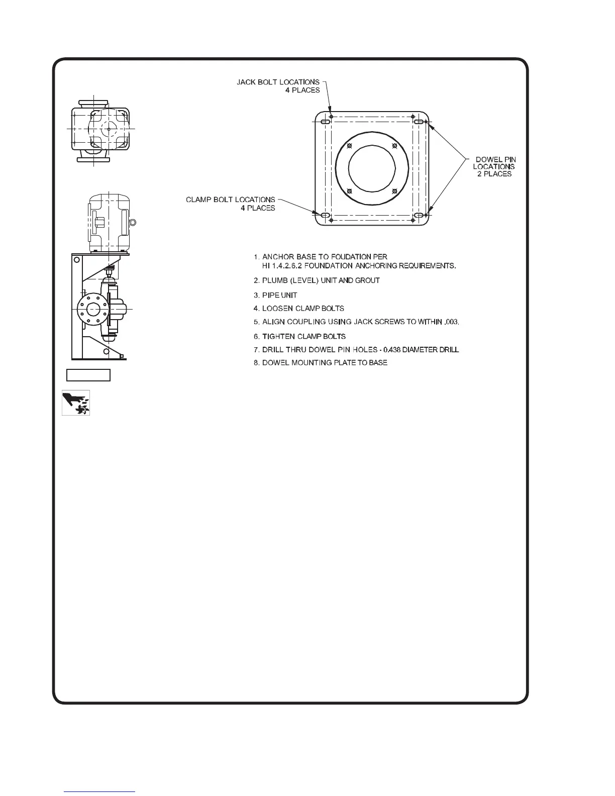
FIELD ALIGNMENT - Vertical Units
To protect the pump and motor during shipment, the motor
and À exible shaft coupling may be shipped unmounted
and must be installed on the pump and properly aligned at
the pump site. Clamp an extender to the pump shaft and
by using a dial indicator, positioned against the ¿ nished
bore of the top plate of the vertical frame, rotate the pump
shaft checking alignment of the pump shaft with the
vertical mounting frame. Use the jackscrews in the base
of the mounting frame or metal shims under the feet of
the pump casing and adjust the pump so that the T.I.R. is
within .004”. Lock jack screws with the jam nuts. The shaft
position in relation to the ¿ nished surface at the top plate of
the mounting frame should be within T.I.R. of .005”.
Install coupling halves on motor shaft and pump shaft but
do not tighten coupling set screws. Position the motor over
the pump and complete the coupling assembly according
to manufacturer’s recommendation, as the motor comes to
rest on the top plate of the vertical mounting frame. Insert
and tighten the motor cap screws.
Using an indicator on both the motor shaft and the pump
shaft, make sure that the shafts are concentric within .004”
and are aligned axially. Tighten coupling set screws.
It is recommended that the motor and pump be dowelled
to the vertical mounting frame when the correct alignment
has been established. Use Loctite on all dowel pins.
5. GROUTING
Grouting compensates for unevenness in the foundation
and prevents vibration and shifting after mounting is
complete. Build a form around the base plate to contain
the grout, and sprinkle area with water to obtain a good
bond. The base should be completely ¿ lled with a good
quality, non-shrinking grout. The usual mixture for grouting
is one part Portland cement and two parts sand with
suf¿ cient water to À ow freely. It is also desirable to grout
the leveling pieces, shims or wedges in place. Foundation
bolts should be fully tightened when grout has hardened,
usually about 48 hours after pouring.
6. PIPING
The pump suction and discharge connections are not
intended to indicate the required suction and discharge
pipe sizes. The pipe diameter must be selected according
to the requirements of the pumping system and
recommended friction losses for the liquid being pumped.
Usually, it is advisable to increase the size of both the
suction and discharge pipes at the pump nozzles to have
minimum acceptable friction loss, suction pipe should
never be smaller in diameter than the pump suction
nozzle. When suction pipe is of larger diameter than the
pump suction nozzle, an eccentric reducer is required to
eliminate possible air or vapor pockets at the pump suction
inlet.
Figure 3