EasyManua.ls Logo

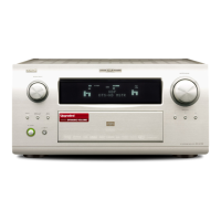
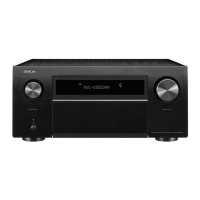
Denon AVC-A11XV Service Manual

Denon AVC-A11XV
172 pages
To Next Page IconTo Next Page
Page #1 background imageLoading...
Page #1 background image
SERVICE MANUAL
AV SURROUND RECEIVER
MODEL AVR-4806
AV SURROUND AMPLIFIER
MODEL AVC-A11XV
For U.S.A., Canada, &
Taiwan R.O.C., model
TOKYO JAPAN
X0228-2 V.02 DE/CDM 0701
Some illustrations using in this service manual are
slightly different from the actual set.
Please use this service manual with referring to the
operating instructions without fail.
For purposes of improvement, specifications and
design are subject to change without notice.
本文中に使用しているイラストは、説明の都合上現物
と多少異なる場合があります。
修理の際は、必ず取扱説明書を参照の上、作業を行っ
てください。
サービスをおこなう前に、このサービスマニュアルを
必ずお読みください。本機は、火災、感電、けがなど
に対する安全性を確保するために、さまざまな配慮を
おこなっており、また法的には「電気用品安全法」に
もとづき、所定の許可を得て製造されております。
従ってサービスをおこなう際は、これらの安全性が維
持されるよう、このサービスマニュアルに記載されて
いる注意事項を必ずお守りください。
本機の仕様は性能改良のため、予告なく変更すること
があります。
補修用性能部品の保有期間は、製造打切後8年です。
注 意
Denon Brand Company, D&M Holdings Inc.
Ver. 2
Please refer to the
MODIFICATION NOTICE.
w
w
w
.
x
i
a
o
y
u
1
6
3
.
c
o
m
Q
Q
3
7
6
3
1
5
1
5
0
9
9
2
8
9
4
2
9
8
T
E
L
1
3
9
4
2
2
9
6
5
1
3
9
9
2
8
9
4
2
9
8
0
5
1
5
1
3
6
7
3
Q
Q
TEL 13942296513 QQ 376315150 892498299
http://www.xiaoyu163.com
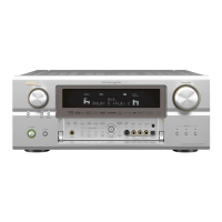
Table of Contents

Other manuals for Denon AVC-A11XV

Questions and Answers:

Denon AVC-A11XV Specifications

General IconGeneral
BrandDenon
ModelAVC-A11XV
CategoryAmplifier
LanguageEnglish

Summary

SAFETY PRECAUTIONS

LEAKAGE CURRENT CHECK

Checks to ensure customer and technician safety by verifying leakage current.

Servicing and Inspection Cautions

General cautions for servicing, including electric shock, disassembly, and part usage.

Inspect for safety after servicing!

Post-servicing checks to ensure all parts are returned correctly and safety is maintained.

Concerning important safety parts

Highlights that many electric/structural parts have special safety properties and must be replaced with designated parts.

DIMENSION

WIRE ARRANGEMENT

Wire arrangement viewed from the top

Illustrates the proper routing of wires when viewed from the top of the unit.

CAUTION IN SERVICING

Initializing AV SURROUND RECEIVER/AMPLIFIER

Procedure for initializing the AV receiver/amplifier after component replacement.

DISASSEMBLY

Top Cover

Procedure for removing the top cover of the unit.

Front Panel

Procedure for removing the front panel of the unit.

Bottom Cover

Procedure for removing the bottom cover of the unit.

P.W.B. Unit of Back Panel

Procedure for removing the P.W.B. unit from the back panel.

Regulator Unit

Procedure for removing the regulator unit assemblies.

Power Amp Unit L/R

Procedure for removing the left/right power amplifier units.

BLOCK DIAGRAMS

AUDIO SECTION

Overview of the audio signal flow and processing within the unit.

Wave form

LEVEL DIAGRAMS

FRONT ch

Level diagram illustrating signal levels for the front audio channel.

CENTER ch

Level diagram illustrating signal levels for the center audio channel.

SUBWOOFER ch

Level diagram illustrating signal levels for the subwoofer audio channel.

SURROUND ch

Level diagram illustrating signal levels for the surround audio channel.

SURROUND BACK ch

Level diagram illustrating signal levels for the surround back audio channel.

LEVEL DIAGRAM

ZONE 2 L/R ch

Level diagram for Zone 2 audio output signals.

ZONE3 L/R ch

Level diagram for Zone 3 audio output signals.

BLOCK DIAGRAMS

AUDIO SECTION

Detailed block diagram of the audio processing sections.

VIDEO SECTION

ADJUSTMENT

AUDIO Section

Procedures for adjusting audio circuit parameters.

IDLING CURRENT (1U-3356-1,2)

Procedure for adjusting idling current on the power amplifier boards.

VIDEO Section

I. MAIN ZONE

Settings and procedures for the main audio/video zone.

SETTING

Initial setup steps for the video section.

BEFORE ADJUSTMENT

Preparation steps required before performing video adjustments.

Procedure

Target, PR/CR-signal

Specific adjustment targets for PR/CR signals during calibration.

SEMICONDUCTORS

IC’s

List and pin descriptions for integrated circuits used in the unit.

BU4094BCF-E2 (IC404) CONNECT P.W.B.

BU4094BCF-E2 Terminal Function

Details the terminal functions for the BU4094BCF-E2 IC.

BU4094BCFV-E2 (IC106,107) CONNECT P.W.B.

BU4094BCFV-E2 Terminal Function

Details the terminal functions for the BU4094BCFV-E2 IC.

MBM29LV160BE90TN (IC506,605,704,804) DIGITAL P.W.B.

Block diagram

Illustrates the internal block diagram of the MBM29LV160BE90TN memory IC.

BR24L02F-WE2 (IC101,102,201,202) D,VIDEO P.W.B.

Block diagram

Illustrates the internal block diagram of the BR24L02F-WE2 EEPROM IC.

M95128-WMN6T (IC410) CONNECT P.W.B.

Pin configuration

Shows the pin configuration of the M95128-WMN6T IC.

SiI9030CUT-7 (IC303) D.VIDEO P.W.B.

Functional Block Diagram

Illustrates the functional block diagram of the SiI9030CUT-7 IC.

SiI9031CUT-7 (IC103,203) D.VIDEO P.W.B.

Functional Block Diagram

Illustrates the functional block diagram of the SiI9031CUT-7 IC.

PCM1804 (IC913) AUDIO P.W.B.

PCM1804 Terminal Function

Details the terminal functions for the PCM1804 audio ADC.

LC89057W-VF4-E (IC101-103) DIGITAL P.W.B.

LC89057W-VF4-E Terminal Function

Details the terminal functions for the LC89057W-VF4-E IC.

LC89057W-VF4-E BLOCK DIAGRAM

LC75721E (IC103,104) FRONT P.W.B.

LC75721E Terminal Function

Details the terminal functions for the LC75721E IC.

PCM1791ADBR (IC901-904) AUDIO P.W.B.

PCM1791 Terminal Function

Details the terminal functions for the PCM1791 DAC.

DM1000 (IC504) DIGITAL P.W.B.

Pin Assignment by Pin Number

Lists pin assignments for the DM1000 IC.

DM1000 (IC701) ETHERNET P.W.B.

M35015-210SP (IC303) A.VIDEO P.W.B.

M35015-210SP Terminal Function

Details the terminal functions for the M35015-210SP IC.

CY7C1049CV33-10ZC (IC802,803) ETHERNET P.W.B.

LMS2021MX (IC707) CONNECT P.W.B.

LMS2021MX Terminal Function

Details the terminal functions for the LMS2021MX IC.

TC94A46FG (IC109) AUDIO P.W.B.

Pin Name

Lists the pin names for the TC94A46FG IC.

TC94A32F (IC301,303,305,307) AUDIO P.W.B.

TC74VHC14FT (IC304,310) DIGITAL P.W.B.

SN65LVDS1DBVR (IC108) D.VIDEO P.W.B.

TC4051BFT (IC120-125,128) A.VIDEO P.W.B.

TC74VHC244FT (IC311) DIGITAL P.W.B.

SN74HC151APW-EL2 (IC953) ETHERNET P.W.B.

SN65LVDS32PW (IC301) DIGITAL P.W.B.

TC74VHCU04FT (IC303,309) DIGITAL P.W.B.

MM74HC4053SJ (IC301) A.VIDEO P.W.B.

CXA1511M (IC503) FRONT P.W.B.

TC9274F-022 (IC120,406) AUDIO P.W.B.

Terminal Functions

Details the terminal functions for the TC9274F-022 IC.

TPS6734IDR (IC508) DIGITAL P.W.B.

LMC6772AIM (IC903,909) DIGITAL P.W.B.

TC74VHCT244AFT (IC401) CONNECT P.W.B.

PQ015EZ5MZ (IC203) DIGITAL P.W.B.

SN65LVDS2DBVR (IC909) CONNECT P.W.B.

TE8200PF (IC305) CONNECT P.W.B.

TC7SZU04F (IC915-918) DIGITAL P.W.B.

TC7SZU04F (IC957,958) ETHERNET P.W.B.

LMS1587CT-ADJ (IC451-453) PRIMALY P.W.B.

PQ20RX11J00H (IC103) PRIMALY P.W.B.

PQ30RV11 (IC101,102,302) PRIMALY P.W.B.

NJM2581M-TE1 (IC101,102) CONNECT P.W.B.

NJM2229M-TE1 (IC306) A.VIDEO P.W.B.

NJM2396F33 (IC407) REGULATOR P.W.B.

NJU7043V (IC906,907) DIGITAL P.W.B.

NJU7223DL1-25 (IC202) DIGITAL P.W.B.

LM1117MPX-1.8 (IC505) DIGITAL P.W.B.

LC72722PM-TLM (IC605) CONNECT P.W.B.

PQ120RDA11J00H (IC701,702,703) REGULATOR P.W.B.

LTC1694CS5 (IC902) CONNECT P.W.B.

LTC4300-2CMS8 (IC903) CONNECT P.W.B.

OTHERS

OPTICAL

Details on optical components used in the unit.

LED

Information regarding LED indicators on the unit.

FL DISPLAY

FLD(32-BT-10GN) (FL101) FRONT P.W.B.

Details about the front panel's FL display module.

Pin connection

Diagram showing the pin connections for the FL display module.

ANODE CONNECTION

PRINTED WIRING BOARDS

1U-3356 AMP P.W.B. UNIT

Component layout diagram for the 1U-3356 amplifier P.W.B.

1U-3667 DIGITAL P.W.B. UNIT (1/2)

1U-3667 DIGITAL P.W.B. UNIT (2/2)

1U-3668 A.VIDEO P.W.B. UNIT (1/2)

1U-3668 A.VIDEO P.W.B. UNIT (2/2)

1U-3669 D.VIDEO P.W.B. UNIT

1U-3670 AUDIO P.W.B. UNIT (1/2)

1U-3670 AUDIO P.W.B. UNIT (2/2)

1U-3671 FRONT P.W.B. UNIT (1/2)

1U-3671 FRONT P.W.B. UNIT (2/2)

1U-3672 PRIMARY P.W.B. UNIT (1/2)

1U-3672 PRIMARY P.W.B. UNIT (2/2)

1U-3673 REGULATOR P.W.B. UNIT (1/2)

1U-3673 REGULATOR P.W.B. UNIT (2/2)

1U-3684 CONNECT P.W.B. UNIT (1/2)

1U-3684 CONNECT P.W.B. UNIT (2/2)

1U-3685 ETHERNET P.W.B. UNIT

1U-3711 XM P.W.B. UNIT (AVR-4806 ONLY)

1U-3712 XM REG. P.W.B. UNIT (AVR-4806 ONLY)

NOTE FOR PARTS LIST

Resistors

Explanation of resistor codes and notations used in the parts list.

Capacitors

Explanation of capacitor codes and notations used in the parts list.

Capacity (electrolyte only)

Notation for electrolyte capacitor capacity values.

Capacity (except electrolyte)

Notation for non-electrolyte capacitor capacity values.

PARTS LIST OF P.W.B. UNIT ASS’Y

00D1U-3356 AMP P.W.B. UNIT ASS'Y

Parts list for the 00D1U-3356 amplifier P.W.B. unit.

RESISTORS GROUP

CAPACITORS GROUP

OTHERS PARTS GROUP

00D1U-3667 DIGITAL P.W.B. UNIT ASS'Y

SEMICONDUCTORS GROUP

Parts list for semiconductors on the 00D1U-3667 digital P.W.B.

CAPACITORS GROUP

OTHERS PARTS GROUP

00D1U-3668 A.VIDEO P.W.B. UNIT ASS'Y

SEMICONDUCTORS GROUP

Parts list for semiconductors on the 00D1U-3668 A.VIDEO P.W.B.

CAPACITORS GROUP

Parts list for capacitors on the 00D1U-3668 A.VIDEO P.W.B.

00D1U-3669 D.VIDEO P.W.B. UNIT ASS'Y

SEMICONDUCTORS GROUP

Parts list for semiconductors on the 00D1U-3669 D.VIDEO P.W.B.

RESISTORS GROUP

Parts list for resistors on the 00D1U-3669 D.VIDEO P.W.B.

CAPACITORS GROUP

Parts list for capacitors on the 00D1U-3669 D.VIDEO P.W.B.

00D1U-3670 AUDIO P.W.B. UNIT ASS'Y

SEMICONDUCTORS GROUP

Parts list for semiconductors on the 00D1U-3670 AUDIO P.W.B.

00D1U-3671 FRONT P.W.B. UNIT ASS'Y

SEMICONDUCTORS GROUP

Parts list for semiconductors on the 00D1U-3671 FRONT P.W.B.

CAPACITORS GROUP

Parts list for capacitors on the 00D1U-3671 FRONT P.W.B.

00D1U-3672 PRIMALY P.W.B. UNIT ASS'Y

SEMICONDUCTORS GROUP

Parts list for semiconductors on the 00D1U-3672 PRIMALY P.W.B.

RESISTORS GROUP

Parts list for resistors on the 00D1U-3672 PRIMALY P.W.B.

CAPACITORS GROUP

Parts list for capacitors on the 00D1U-3672 PRIMALY P.W.B.

SEMICONDUCTORS GROUP

OTHERS PARTS GROUP

00D1U-3673 REGULATOR P.W.B. UNIT ASS'Y

SEMICONDUCTORS GROUP

Parts list for semiconductors on the 00D1U-3673 REGULATOR P.W.B.

RESISTORS GROUP

Parts list for resistors on the 00D1U-3673 REGULATOR P.W.B.

CAPACITORS GROUP

Parts list for capacitors on the 00D1U-3673 REGULATOR P.W.B.

OTHERS PARTS GROUP

SEMICONDUCTORS GROUP

OTHERS PARTS GROUP

00D1U-3671 FRONT P.W.B. UNIT ASS'Y

SEMICONDUCTORS GROUP

Parts list for semiconductors on the 00D1U-3671 FRONT P.W.B.

00D1U-3672 XM REG P.W.B. UNIT ASS'Y

SEMICONDUCTORS GROUP

Parts list for semiconductors on the 00D1U-3672 XM REG P.W.B.

EXPLODED VIEWS

Parts List

List of parts shown in the exploded view diagrams.

PARTS LIST OF EXPLODED VIEW

SCREWS

PARTS LIST OF PACKING & ACCESSORIES

WIRING DIAGRAM

NOTE FOR SCHEMATIC DIAGRAM

SCHEMATIC DIAGRAMS (1/35)

1U-3356 AMP UNIT

Schematic diagram for the 1U-3356 amplifier unit.

1U-3356-1 AMP L UNIT

Schematic diagram for the 1U-3356-1 amplifier L unit.

1U-3356-2 AMP R UNIT

Schematic diagram for the 1U-3356-2 amplifier R unit.

SCHEMATIC DIAGRAMS (2/35)

1U-3667 DIGITAL UNIT (1/10)

Schematic diagram for the 1U-3667 digital unit, part 1 of 10.

SCHEMATIC DIAGRAMS (3/35)

1U-3667 DIGITAL UNIT (2/10)

Schematic diagram for the 1U-3667 digital unit, part 2 of 10.

SCHEMATIC DIAGRAMS (4/35)

1U-3667 DIGITAL UNIT (3/10)

Schematic diagram for the 1U-3667 digital unit, part 3 of 10.

SCHEMATIC DIAGRAMS (5/35)

1U-3667 DIGITAL UNIT (4/10)

Schematic diagram for the 1U-3667 digital unit, part 4 of 10.

SCHEMATIC DIAGRAMS (6/35)

1U-3667 DIGITAL UNIT (5/10)

Schematic diagram for the 1U-3667 digital unit, part 5 of 10.

SCHEMATIC DIAGRAMS (7/35)

1U-3667 DIGITAL UNIT (6/10)

Schematic diagram for the 1U-3667 digital unit, part 6 of 10.

SCHEMATIC DIAGRAMS (8/35)

1U-3667 DIGITAL UNIT (7/10)

Schematic diagram for the 1U-3667 digital unit, part 7 of 10.

SCHEMATIC DIAGRAMS (9/35)

1U-3667 DIGITAL UNIT (8/10)

Schematic diagram for the 1U-3667 digital unit, part 8 of 10.

SCHEMATIC DIAGRAMS (10/35)

1U-3667 DIGITAL UNIT (9/10)

Schematic diagram for the 1U-3667 digital unit, part 9 of 10.

SCHEMATIC DIAGRAMS (11/35)

1U-3667 DIGITAL UNIT (10/10)

Schematic diagram for the 1U-3667 digital unit, part 10 of 10.

SCHEMATIC DIAGRAMS (12/35)

1U-3668 A.VIDEO UNIT (1/2)

Schematic diagram for the 1U-3668 A.VIDEO unit, part 1 of 2.

SCHEMATIC DIAGRAMS (13/35)

1U-3668 A.VIDEO UNIT (2/2)

Schematic diagram for the 1U-3668 A.VIDEO unit, part 2 of 2.

SCHEMATIC DIAGRAMS (14/35)

1U-3669 D.VIDEO UNIT (1/3)

Schematic diagram for the 1U-3669 D.VIDEO unit, part 1 of 3.

SCHEMATIC DIAGRAMS (15/35)

1U-3669 D.VIDEO UNIT (2/3)

Schematic diagram for the 1U-3669 D.VIDEO unit, part 2 of 3.

SCHEMATIC DIAGRAMS (16/35)

1U-3669 D.VIDEO UNIT (3/3)

Schematic diagram for the 1U-3669 D.VIDEO unit, part 3 of 3.

SCHEMATIC DIAGRAMS (17/35)

1U-3670 AUDIO UNIT (1/4)

Schematic diagram for the 1U-3670 AUDIO unit, part 1 of 4.

SCHEMATIC DIAGRAMS (18/35)

1U-3670 AUDIO UNIT (2/4)

Schematic diagram for the 1U-3670 AUDIO unit, part 2 of 4.

SCHEMATIC DIAGRAMS (19/35)

1U-3670 AUDIO UNIT (3/4)

Schematic diagram for the 1U-3670 AUDIO unit, part 3 of 4.

SCHEMATIC DIAGRAMS (20/35)

1U-3670 AUDIO UNIT (4/4)

Schematic diagram for the 1U-3670 AUDIO unit, part 4 of 4.

SCHEMATIC DIAGRAMS (21/35)

1U-3671 FRONT UNIT (1/2)

Schematic diagram for the 1U-3671 FRONT unit, part 1 of 2.

SCHEMATIC DIAGRAMS (22/35)

1U-3671 FRONT UNIT (2/2)

Schematic diagram for the 1U-3671 FRONT unit, part 2 of 2.

SCHEMATIC DIAGRAMS (23/35)

1U-3672 PRIMARY UNIT (1/2)

Schematic diagram for the 1U-3672 PRIMARY unit, part 1 of 2.

SCHEMATIC DIAGRAMS (24/35)

1U-3672 PRIMARY UNIT (2/2)

Schematic diagram for the 1U-3672 PRIMARY unit, part 2 of 2.

SCHEMATIC DIAGRAMS (25/35)

1U-3673 REGULATOR UNIT (1/2)

Schematic diagram for the 1U-3673 REGULATOR unit, part 1 of 2.

SCHEMATIC DIAGRAMS (26/35)

1U-3673 REGULATOR UNIT (2/2)

Schematic diagram for the 1U-3673 REGULATOR unit, part 2 of 2.

SCHEMATIC DIAGRAMS (27/35)

1U-3684 CONNECT UNIT (1/6)

Schematic diagram for the 1U-3684 CONNECT unit, part 1 of 6.

SCHEMATIC DIAGRAMS (28/35)

1U-3684 CONNECT UNIT (2/6)

Schematic diagram for the 1U-3684 CONNECT unit, part 2 of 6.

SCHEMATIC DIAGRAMS (29/35)

1U-3684 CONNECT UNIT (3/6)

Schematic diagram for the 1U-3684 CONNECT unit, part 3 of 6.

SCHEMATIC DIAGRAMS (30/35)

1U-3684 CONNECT UNIT (4/6)

Schematic diagram for the 1U-3684 CONNECT unit, part 4 of 6.

SCHEMATIC DIAGRAMS (31/35)

1U-3684 CONNECT UNIT (5/6)

Schematic diagram for the 1U-3684 CONNECT unit, part 5 of 6.

SCHEMATIC DIAGRAMS (32/35)

1U-3684 CONNECT UNIT (6/6)

Schematic diagram for the 1U-3684 CONNECT unit, part 6 of 6.

SCHEMATIC DIAGRAMS (33/35)

1U-3685 ETHERNET UNIT (1/1)

Schematic diagram for the 1U-3685 ETHERNET unit.

SCHEMATIC DIAGRAMS (34/35)

1U-3711 XM UNIT

Schematic diagram for the 1U-3711 XM unit.

SCHEMATIC DIAGRAMS (35/35)

1U-3712 XM REG UNIT

Schematic diagram for the 1U-3712 XM REG unit.

Related product manuals