r
2-2 Speaker System Connections
• This receiver can accommodate connections of a total of eight
speakers including two set of (front) main amplifier speakers
(A
and 8), one set of rear speakers, and one or two center
speakers.
• Connect the speaker terminals with the speakers making sure
that like polarities are matched
(EB
with
EB, 8
with
8).
Mismatching of polarities will result in weak central sound,
unclear orientation of the various instruments, and the sense
of direction of the stereo being impaired.
• When making connections, take care that none of the indi-
vidual conductors of the speaker cord come in contact with
adjacent terminals, with other speaker cord conductors, or
with the rear panel.
• Speaker Impedance
• When speaker systems A and 8 are use separately,
speakers with an impedance of from
6
to
16 () lohms
can
be connected.
• 8e careful when using two pairs of main speakers
(A
+8) at
the same time, since use of speakers with an impedance
outside the range of
12
to
16 () lohms
will
lead
to damage.
• Speakers with an impedance of
6
to
12 () lohms
can be
connected for use as center and rear speakers.
• The protection circuit may operate or damage may occur
when speakers with an impednce outside of the above
range are used.
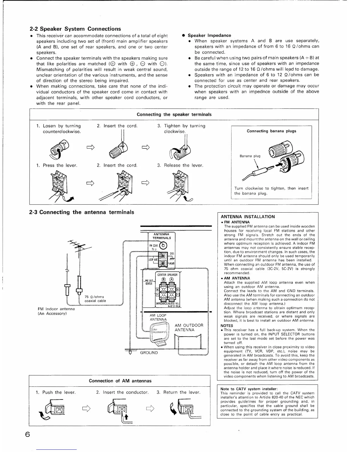
Connecting the speaker terminals
1.
Losen by turning
2.
Insert the cord.
counterclockwise.
J
,
¢ ¢
1.
Press the lever.
2.
Insert the cord.
'v
¢/J
¢
2-3 Connecting the antenna terminals
3.
Tighten by turning
clockwise.
~
3.
Release the lever.
ANTENNA
TERMINALS
FMCOAX.®
JSu
~
GNO.
!
lOOP~
i
*
.
AM
I
CENTER SPEAKER
_PFlEOUT
,® ~
I
CEIITER
+
Yl
1+
I
-
-
I
IMPEOANCE/A~:6'16Ii
A.8:12·161
.
-
AM LOOP
ANT~
LI
v-
'j
AM OUTDOOR
!
(An
ANTENNA
!
Accessorvl
i •...
-"
~I;
~
II
~
'1/"
'1111
GROUND
1
~ " O'o"m,
coaxial cable
FM Indoor antenna
(An Accessory)
Connection of AM antennas
2. Insert the conductor.
3. Return the lever.
1. Push the lever.
6
Connecting banana plugs
Turn clockwise to tighten, then insert
the banana plug.
ANTENNA
INSTALLATION
• FM ANTENNA
The supplied FM antenna can be used inside wooden
houses for receiving local FM stations and other
strong FM signals. Stretch out the ends of the
antenna and mount the antenna on the wall or ceiling
where optimum reception is achieved. A indoor FM
antennas may not consistently ensure stable recep-
tion, due to environment changes. In such cases, the
indoor FM antenna should only be used temporarily
until an outdoor FM antenna has been installed.
When connecting an outdoor FM antenna, the use of
75 ohm coaxial cable (3C-2V, 5C-2V) is strongly
recommended.
• AM ANTENNA
Attach the supplied AM loop antenna even when
using an outdoor AM antenna.
Connect the leads to the AM and GND terminals.
Also use the AM terminals for connecting an outdoor
AM antenna (when making such a connection do not
disconnect the AM loop antenna.)
Adjust the loop antenna to obtain optimum recep-
tion. Where broadcast stations are distant and only
weak signals are received, or where signals are
blocked, it is best to install an outdoor AM antenna.
NOTES
• This receiver has a full back-up system. When the
power is turned on, the INPUT SELECTOR buttons
are set to the last mode set before the power was
turned
off.
• When using this receiver in close proximity to video
equipment (TV, VCR, VDP, etc.), noise may be
generated in AM broadcasts. To avoid this, keep the
receiver as far away from other video components as
possible, or detach the AM loop antenna from the
antenna holder and place it where noise is reduced. If
the noise is not reduced, turn
off
the power of the
video components when listening to AM broadcasts.
Note to CATV system installer:
This reminder is provided to call the CATV system
installer's attention to Article 820-40 of the NEe which
provides guidelines for proper grounding and, in
particular, specifies that the cable ground shall be
connected to the grounding system of the building, as
close to the point of cable entry as practical.
 Loading...