EasyManua.ls Logo

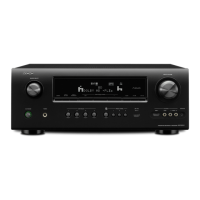
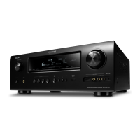
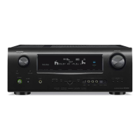
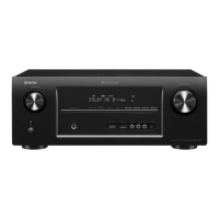
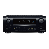
Denon AVR-2312 Service Manual

Denon AVR-2312
226 pages
To Next Page IconTo Next Page
Page #1 background imageLoading...
Page #1 background image
D&M Holdings Inc.
SERVICE MANUAL
e
e
MODEL JP E3 E2 EK EA E1C E1K CI
AVR-2312CI
P
AVR-2312
P P P
INTEGRATED NETWORK AV RECEIVER
Ver. 5
S0376-0V05DM/DG1110
Some illustrations using in this service manual are slightly different from the actual set.
Please use this service manual with referring to the operating instructions without fail.
• For purposes of improvement, specications and design are subject to change without notice.
s ss
Please refer to the
MODIFICATION NOTICE.

Table of Contents

Other manuals for Denon AVR-2312

Questions and Answers:

Denon AVR-2312 Specifications

General IconGeneral
Impedance8 Ω
Speaker selectorA+B
Input sensitivity200 mV
Pre-out connectivityYes
Audio output channels7.1 channels
Audio A/D Converter (ADC)24-bit/96kHz
Signal-to-Noise Ratio (SNR)100 dB
Total Harmonic Distortion (THD)0.08 %
Power output per channel (1KHz@8 Ohm)135 W
Power output per channel (20-20KHz@8 Ohm)105 W
HDMI in7
Composite video in4
Ethernet LAN (RJ-45) ports1
Multichannel audio input typeRCA
Component video (YPbPr/YCbCr) in2
Headphone connectivity6.3 mm
Connectivity technologyWired
Speakers connectivity typeBinding post
Audio formats supportedAAC, FLAC, MP3, WAV, WMA
Image formats supportedJPG
Wi-FiNo
AM band range522 - 1611 kHz
FM band range87.5 - 108 MHz
Supported radio bandsAM, FM
Preset stations quantity56
Internet radio services supportedLast.fm, Napster
Supported video modes1080i, 1080p, 480i, 480p, 576i, 576p, 720p
DisplayVFD
HDMI version1.4a
Product colorBlack
Audio decodersDolby Pro Logic IIz, Dolby TrueHD, DTS-HD Master Audio
Volume controlRotary
Apple docking compatibilityiPad, iPhone, iPod
Number of products included1 pc(s)
AC input voltage230 V
AC input frequency50 Hz
Power consumption (standby)0.1 W
Power consumption (typical)600 W
Weight and Dimensions IconWeight and Dimensions
Depth382 mm
Width434 mm
Height167 mm
Weight11000 g

Summary

Safety Precautions

Leakage Current Check

Procedure for checking leakage current before returning the set to the customer.

Cautions in Servicing

General cautions and instructions for servicing and inspection.

Technical Specifications

Disassembly

Special Mode

Special Mode Setting Button

Explains how to set special modes using buttons.

1. µcom/DSP Version Display Mode

1.3. Error Display

Trouble shooting

Lists strategies to resolve identified error codes.

2. Errors Checking Mode (Displaying the Protection History)

2.2. About the Display on the FL Display

Details what is displayed on the FL display for different protection incidents.

2.3. Clearing the Protection History

Warning Indication by the POWER LED

Indicates warnings shown by the POWER LED based on protection incident conditions.

3. Remote ID Setup Mode

2.2. Setting the AV Receivers

Steps to set up AV receivers for Remote ID.

2.2. Setting the Remote Control Unit

Steps to set the remote control unit for Remote ID.

4. Diagnostic Mode (Video/Audio (Signal) Path Confirmation Mode)

4.1. Starting Diagnostic Mode

Instructions on how to start the diagnostic mode.

4.2. Canceling Diagnostic Mode

Instructions on how to cancel the diagnostic mode.

4.4. Video System Confirmation Items

Lists video system confirmation items and their details.

3.5. Audio System Confirmation Items

Block Diagram

AVR3312/2312 VCC Block Diagram

JIG FOR SERVICING

Connection table of Board to Board

When the Microprocessor is Replaced with a New One

Procedure for Upgrading the Version of the Firmware

1.2. Checking and Updating the Firmware

Steps to check for and update the firmware.

1.3. About the Error Code

Error Code

Lists error codes related to firmware updates.

Details of Error code

Provides details of each error code.

Coping strategies

Lists strategies to resolve identified error codes.

Device Display During Firmware Update

Adjustment

Adjusting Idling Current

Procedure for adjusting idling current for the audio section.

2. Adjustment

Detailed steps for performing the adjustment.

Surround Modes and Parameters

Surround modes and surround parameters

Shows available surround modes and adjustable parameters.

n Types of Input Signals, and Corresponding Surround Modes

Trouble Shooting

1. Power

Troubleshooting steps for power-related issues.

1.1. Power Not Turn On

Flowchart for diagnosing power-on issues.

1.2. Fuse is Blown

Troubleshooting steps when a fuse is blown.

2. Analog Video

VIDEO B'D flaw.

HDMI Test Point

VIDEO Test Point

3. HDMI/DVI

3.1. No Picture or Sound is Output (HDMI to HDMI)

Troubleshooting flowchart for no picture or sound issues over HDMI.

Check TV

The set does not recognize the TV.

Diagnoses issues when the set does not recognize the TV.

Check operation of IC121(ADV7844).

Check operation of IC151(ADV8002).

3.2. HDMI Test Point and Waveforms

Detail C

Detail D

Detail E

DDC_CLK/DDC_DATA/TMDS : Check items (17)/(19)/(24)/(32)

Timing waveform illustration from the start of CEC3.3V to when reset is released : Check items (22)

Timing waveform illustration from the start of CEC3.3V to when reset is released : Check items (23)

Timing waveform illustration from the start of CEC3.3V to when reset is released : Check items (31)

Timing waveform illustration from the start of CEC3.3V to when reset is released : Check items (27)

HD_DE/HD_VSYNC/HD_HSYNC/HD_PCLK : Check items (28)

4. AUDIO

4.1. AUDIO CHECK

Troubleshooting flowchart for audio output issues.

4.2. Power AMP (Main Unit)

4.3. Analog Audio

5. Network/USB

5.1. Cannot Connect to Network

Troubleshooting steps for network connectivity issues.

Checking the Settings

Verifies network settings on the receiver and peripherals.

5.2. USB Device is Not Recognized

Checking the USB Device

Steps to check the USB device and its compatibility.

Checking the Set (AV Receiver)

Checks the AV receiver's USB connection and power.

5.3. No Picture or Sound is Output

Checking the Set (AV Receiver):(If no picture is output)

Checks video signals for no picture output.

Checking the Set (AV Receiver):(If no sound is output)

Checks S/PDIF signals for no sound output.

HDMI Test Point

USB Test Point

6. SMPS

Is there damage in IC901 (TOP258MG)?

Checks for damage in IC901.

Is the fuse (F9001) blown?

Checks if the fuse is blown.

Operation Waveform for Each Part

SMPS Unit

Set

Audio Check PATH

Clock Flow & Wave Form in Digital Block

Level Diagram

Printed Wiring Boards

SMPS (Component Side)

SMPS (Foil Side)

SPK_PREOUT (Component Side)

SPK_PREOUT (Foil Side)

INPUT (Component Side)

INPUT (Foil Side)

FUSE (Component Side)

FUSE (Foil Side)

RS232C_CNT (Component Side)

RS232C_CNT (Foil Side)

FRONT (Component Side)

FRONT (Foil Side)

V.AUX (Component Side)

V.AUX (Foil Side)

HDMI FFC (Component Side)

HDMI FFC (Foil Side)

USB (Component Side)

USB (Foil Side)

SELECTOR (Component Side)

SELECTOR (Foil Side)

RS232C (Component Side)

RS232C (Foil Side)

SIDE_CNT (Component Side)

SIDE_CNT (Foil Side)

VIDEO (Component Side)

VIDEO (Foil Side)

FRONT CNT (Component Side)

FRONT CNT (Foil Side)

HDMI (Component Side)

HDMI (Foil Side)

Wiring Diagram

Exploded View

Parts List of Exploded View

Parts List of Packing & Accessories

SEMICONDUCTORS

1. IC's

Pin descriptions and functions for IC201 (R5F5630ECDFB).

R5F5630ECDFB Terminal Functions

ADV3002BSTZ Block diagram

AD8195ACPZ Pin Function

AD8195ACPZ Block diagram

LC89058W-E (HDMI : IC403,IC404,IC405)

Pin Functions

Lists pin names, I/O, and functions for LC89058W-E.

LC89058W-E Block diagram

ADSP21487KSWZ-4B (HDMI : IC408)

ADSP21487KSWZ Terminal Function

Lists pin names, I/O, and functions for ADSP21487KSWZ.

W9864G6JH-6 (HDMI : IC409)

W9864G6JH-6 Block diagram

Block diagram for the W9864G6JH-6 memory chip.

W9864G6JH-6 Block diagram

W9864G6JH-6 Pin description

MX29LV160DBTI-70G (HDMI : IC410)

MX29LV160DBTI-70G Block Diagram

Block diagram for the MX29LV160DBTI-70G flash memory.

AK4424ET (HDMI : IC455,IC457)

AK4424ET Block Diagram

Block diagram for the AK4424ET DAC converter.

AK5358BET (HDMI : IC451)

AK5358BET Pin Function

Lists pin names, I/O, and functions for AK5358BET ADC.

AK4358VQ (HDMI : IC441)

AK4358VQ Pin Function

Lists pin names, I/O, and functions for AK4358VQ DAC.

H27U1G8F2BTR-BC (HDMI : IC 391)

H27U1G8F2BTR-BC Pin Function

Lists pin names and functions for H27U1G8F2BTR-BC NAND Flash.

H27U1G8F2BTR-BC Block Diagram

Block diagram for the H27U1G8F2BTR-BC NAND Flash.

W9825G6JH-6 (HDMI : IC392)

W9825G6JH-6 Block Diagram

Block diagram for the W9825G6JH-6 SDRAM.

W9825G6JH-6 Pin Function

Lists pin names and functions for W9825G6JH-6 SDRAM.

LAN8700 (HDMI : IC322)

LAN8700 Block Diagram

Block diagram for the LAN8700 Ethernet PHY.

LAN8700 Pin Description

SAA7121 (HDMI : IC323)

SAA7121 Block Diagram

Block diagram for the SAA7121 Video Encoder.

SAA7121 Pin Description

R2A15220FP (AUDIO : IC471)

R2A15220FP Pin Function

Lists pin names and functions for R2A15220FP audio IC.

NJW1194A (AUDIO : IC484,IC489)

NJW1194A Block Diagram

Block diagram for the NJW1194A audio IC.

2. FL DISPLAY

ANODE CONNECTION

PARTS LIST OF P.C.B. UNIT

PCB FRONT ASSY

PCB 7CH AMP ASSY

PCB MAIN ASSY

PCB CNT ASSY

PCB VIDEO ASSY

PCB HDMI ASS'Y

PCB SMPS ASSY

Related product manuals