


D
Debra RubioAug 14, 2025
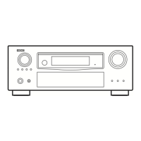
What to do if my Denon AVR-3801 Stereo Receiver display is lit but there's no sound?
- FfmillerAug 14, 2025
If your Denon Stereo Receiver's display is lit but no sound is produced, consider these potential causes: * **Speaker cords:** Ensure they are securely connected. * **Audio function button:** Make sure it is in the correct position. * **Volume:** Increase the volume level. * **Muting:** Check if muting is enabled and switch it off. * **Digital signals:** If using digital input, ensure digital signals are being input or that you've selected the correct input jacks.