EasyManua.ls Logo

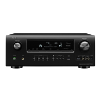
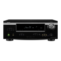
Denon AVR-391 Service Manual

Denon AVR-391
111 pages
To Next Page IconTo Next Page
Page #1 background imageLoading...
Page #1 background image
D&M Holdings Inc.
SERVICE MANUAL
e
e
Copyright 2010 D&M Holdings Inc. All rights reserved.
WARNING: Violators will be prosecuted to the maximum extent possible.
MODEL JP E3 E3B E2 EK EA E1 E1C
AVR-1311
33
AVR-391
33
AV SURROUND RECEIVER
MODEL JP E3 E3B E2 EK EA E1 E1C
DHT-1311XP
3
DHT-391XP
33 3
5.1CH HOME THEATER SYSTEM
Ver. 3
•
Some illustrations using in this service manual are slightly different from the actual set.
•
Please use this service manual with referring to the operating instructions without fail.
•
For purposes of improvement, speci cations and design are subject to change without notice.
S0141-0V03DM/DG1010
s
Please refer to the
MODIFICATION NOTICE.
Other manuals for Denon AVR-391

Questions and Answers:

Denon AVR-391 Specifications

General IconGeneral
Number of Channels5.1
HDMI Inputs4
HDMI Outputs1
Dolby FormatsDolby Digital, Dolby Pro Logic II
Audio Return ChannelYes
Component Video Inputs2
Digital Optical Inputs1
Digital Coaxial Inputs1
Response Bandwidth10 Hz - 100 kHz
Signal-To-Noise Ratio98 dB
THD0.08%
Input Impedance47 kOhms
Input Sensitivity200 mV
Tuner BandsAM/FM
Power Output75 Watts per channel
DTS FormatsDTS
Tuner Frequency RangeFM: 87.5 - 108 MHz
Video Inputs/OutputsComposite
Audio Inputs/OutputsDigital Optical
Dimensions434 x 151 x 319 mm
Weight8.5 kg

Summary

SAFETY PRECAUTIONS

LEAKAGE CURRENT CHECK

Procedure for checking leakage current before returning the unit.

Servicing and Inspection Cautions

Points to heed during servicing, covering electric shock and part handling.

Important Safety Parts Cautions

Importance of using designated parts for safety properties.

TECHNICAL SPECIFICATIONS

Audio Section Specifications

Details power amplifier ratings, input sensitivity, and frequency response.

Tuner Section Specifications

Covers receiving ranges, sensitivity, and distortion for FM/AM.

General Specifications

Includes power supply, consumption, external dimensions, and weight.

DISASSEMBLY

FRONT PANEL ASSY Disassembly

Steps for removing the front panel assembly from the unit.

HDMI UNIT Disassembly

Procedure for removing the HDMI unit.

POWER UNIT Disassembly

Procedure for disassembling the power unit.

VERSION UPGRADE PROCEDURE OF FIRMWARE

Firmware Upgrade Preparations

Required items and PC setup for firmware update.

UPDATE FIRMWARE

Step-by-step guide for updating the AV receiver firmware.

ADJUSTMENT

Audio Section Adjustment

Procedure for adjusting the audio section, focusing on idling current.

Idling Current Adjustment

Detailed steps for setting the idling current for audio channels.

TROUBLE SHOOTING

Power Issues

Troubleshooting steps for power-related problems like no turn-on.

Analog Video Issues

Troubleshooting guide for analog video output problems.

HDMI/DVI Issues

Steps to resolve no picture or sound output via HDMI/DVI.

PRINTED WIRING BOARDS

FRONT PWB Component Side

Component layout diagram for the front printed wiring board.

MAIN PWB Component Side

Component layout diagram for the main printed wiring board.

INPUT PWB Component Side

Component layout diagram for the input printed wiring board.

SCHEMATIC DIAGRAMS (1/1)

Related product manuals