


M
Matthew BrownSep 23, 2025
What to do if “Code? [ ]” is displayed in the SIRIUS mode on Denon Stereo Receiver?
- CCassandra RobinsonSep 23, 2025
If “Code? [ ]” is displayed in the SIRIUS mode, insert the password (4 digits) into “[ ]”.
What to do if “Code? [ ]” is displayed in the SIRIUS mode on Denon Stereo Receiver?
If “Code? [ ]” is displayed in the SIRIUS mode, insert the password (4 digits) into “[ ]”.
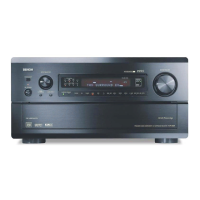
What to do if no sound is produced from subwoofer on Denon Stereo Receiver?
If there's no sound from the subwoofer, ensure the subwoofer's power is on. Check that the “Subwoofer” setting at “Speaker Setup” is set to “Yes”. Verify the subwoofer is properly connected and adjust its volume to an appropriate level.
What to do if there is no sound from center speaker on Denon AVR-589?
If no sound is coming from the center speaker, and you are playing a monaural source (TV, AM radio broadcast, etc.) in “STANDARD” (Dolby/ DTS Surround) mode, change the mode to something other than “STANDARD” (Dolby/ DTS Surround).
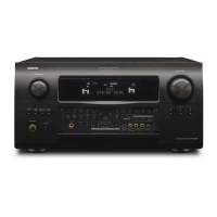
How to fix no HDMI audio signals from Denon AVR-589 Stereo Receiver speakers?
The audio signal input to the HDMI input connector cannot be played on the AVR-589. Input the audio signal to the digital audio input connector or analog audio input connector.
Why is there no sound from surround speakers on my Denon Stereo Receiver?
If no sound is produced from the surround speakers, and the surround mode is set to “STEREO” or “DIRECT”, set the receiver to a surround playback mode.
What to do if “ANTENNA ERROR” is displayed in the SIRIUS mode on Denon AVR-589 Stereo Receiver?
If “ANTENNA ERROR” is displayed in the SIRIUS mode, check that the connections are correct.
How to fix no picture on Denon AVR-589 Stereo Receiver?
If no picture appears, check the connections between the AVR-589 and the monitor. The connection terminal of the AVR-589 and the connection terminal of the monitor should be of the same type, as video signals are output in the same format as the input signals.
What to do if “CHECK SR TUNER” is displayed in the SIRIUS mode on Denon Stereo Receiver?
If “CHECK SR TUNER” is displayed in the SIRIUS mode, check that the connections are correct.
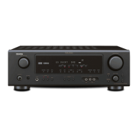
Why does my Denon AVR-589 Stereo Receiver keep turning off?
The Denon Stereo Receiver may be turning off due to the protection circuit being activated by a temperature rise in the unit's internal parts. Immediately switch off the power, and re-apply it after the body temperature has sufficiently cooled. Re-install the unit in a location with good ventilation.
Why does Denon AVR-589 Stereo Receiver power switch off suddenly?
The Denon Stereo Receiver may suddenly switch off if speakers have impedance lower than specified, or if speaker cable core wires touch each other or the AVR-589 rear panel. To resolve this, use speakers with the specified impedance. Unplug the power cord, twist the core wires together tightly or effect termination treatments, and then reconnect.
Crucial safety check before returning unit to customer to ensure protection.
Cautions for servicing, electric shock, disassembly, parts usage, and wiring.
Explanation of parts marked with 'z' that have critical safety characteristics.
Outlines the sequence for dismantling and reassembling components correctly.
Shows the disassembly steps with corresponding image references for clarity.
Describes the procedure for initializing the AV receiver or amplifier after component replacement.
Lists required jigs and tools for board repair and firmware updates.
Describes how to enter and use the error history display mode.
Explains how protection history is displayed on the FL display.
Details methods for clearing the protection history.
Details the steps to adjust the idling current using test points and controls.
Provides a flowchart to diagnose power-on problems.
Guides through troubleshooting steps for a blown fuse.
Details checks for video output issues on the AVR-1709 model.
Details checks for video output issues on the AVR-1609 model.
Provides a flowchart for diagnosing HDMI/DVI output issues.
Shows the main unit's schematic diagram.
Shows schematics for input, CPU, and front units.
Shows schematics for HDMI, Sirius, and video units.
Shows schematics for power and 2CH amplifier units.
| Input Sensitivity | 200 mV |
|---|---|
| HDMI Switching | Yes |
| Frequency Response | 10Hz-100kHz |
| Inputs | 4 x composite |
| Outputs | 1 x HDMI |
| Input Impedance | 47 kΩ |
| Tuner Type | Digital |
| Tuner Bands | AM/FM |
| Audio D/A Converter | 192 kHz/24-bit |
| Tuner Frequency Range | FM: 87.5 - 108 MHz |
| Dimensions (W x H x D) | 434 x 171 x 377 mm |