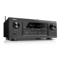
Proceeding : TOP COVER → WiFi ANT → DIGITAL PCB → VIDEO PCB
(1) Remove the connector.
5. VIDEO PCB
CUT
CUT
N5000
CN5003
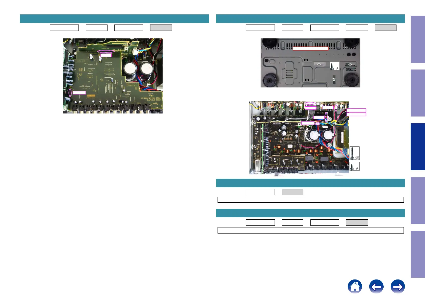
Proceeding : TOP COVER → WiFi ANT → DIGITAL PCB → VIDEO PCB → MAIN PCB
(1) Remove the screws.
(2) Remove the screws. Remove the connector.
Proceeding : TOP COVER → SMPS PCB
See "EXPLODED VIEW" for instructions on removing the SMPS PCB.
Proceeding : TOP COVER → COVER → DIGITAL PCB → TRANS
See "EXPLODED VIEW" for instructions on removing the transformer (TRANS).
6. MAIN PCB
View from the bottom
x3
x2
x8
from CP405
from CP403
CP402
CP401
CP401
CP5003
7. SMPS PCB
8. TRANS
69
Caution in
servicing
Electrical Mechanical Repair Information Updating
 Loading...