When the results of check item (3-10.3.) are "00"
(Detection of 5V is not OK.)
When the results of check item (3-10.4.) are "00 or 04"
(If the DDC are not OK)
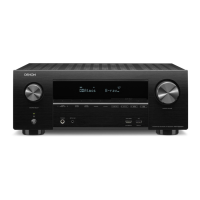
Check item(3-10.5.). Check the +5V voltage.
Does "+5 V" at the following test point indicate 5V?
The test points are as follows. (HDMI SW [IC701])
JK702
HDMI OUT
[F-HDMI]
+5V_F
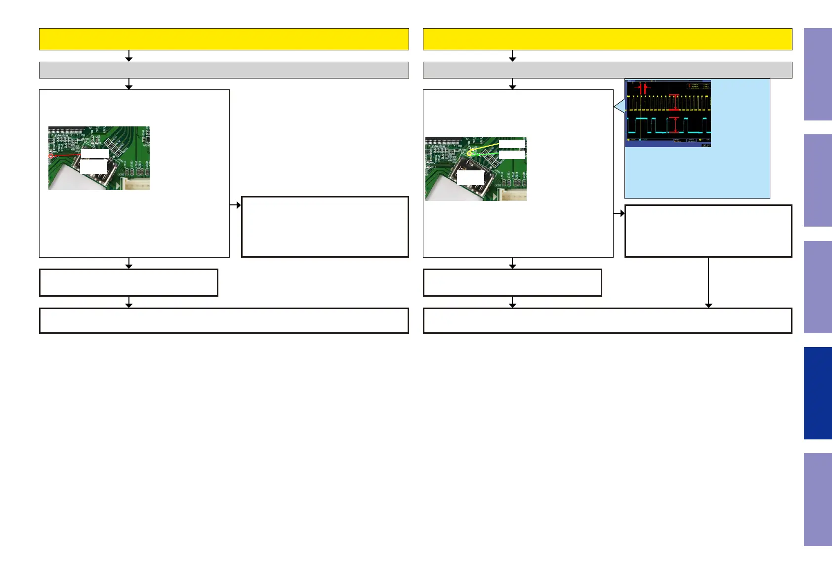
Check item(3-10.6.). Check the DDC line :
Does "DDCCL" and " DDCDA" signal of the HDMI SW
[IC701] indicate 5 V?
The test points are as follows.
JK702
HDMI OUT
[F-HDMI]
DA_F
CK_F
Check the +5V voltage. (HDMI DDC Buffer) Check the DDC Line. (HDMI DDC Buffer)
HDMI SW [IC701] is faulty.
Replace with a new device.
Recheck from check item (3.2.).
If it does not work, replace the PCB.
Recheck from check item (3.2.).
If it does not work, replace the PCB.
HDMI SW [IC701] is faulty.
Replace with a new device.
Check for a short circuit in the 5V line, the
Front HDMI FFC, and the 5V Switch [IC733].
If there is no problem, the HDMI SW1[IC701]
or 5V Switch[IC733] is faulty.
Replace with a new device.
Check for a short circuit in the DDC line and
check the FRONT HDMI Cable.
If there is no problem, the HDMI DDC Buffer
[IC311] is faulty.
Replace with a new device.
YESYES
NO
NO
less than 100KHz
5V
5V
This diagram shows an example of the DDC commu-
nication waveform.
-The high level voltage is 5V.
-The frequency of the DDC CLK is 100 KHz or less.
Check at each test point.
Voltage scale:2.0V/div
Time scale:40us/div
Before Servicing
This Unit
Electrical Mechanical Repair Information Updating
106

 Loading...