A
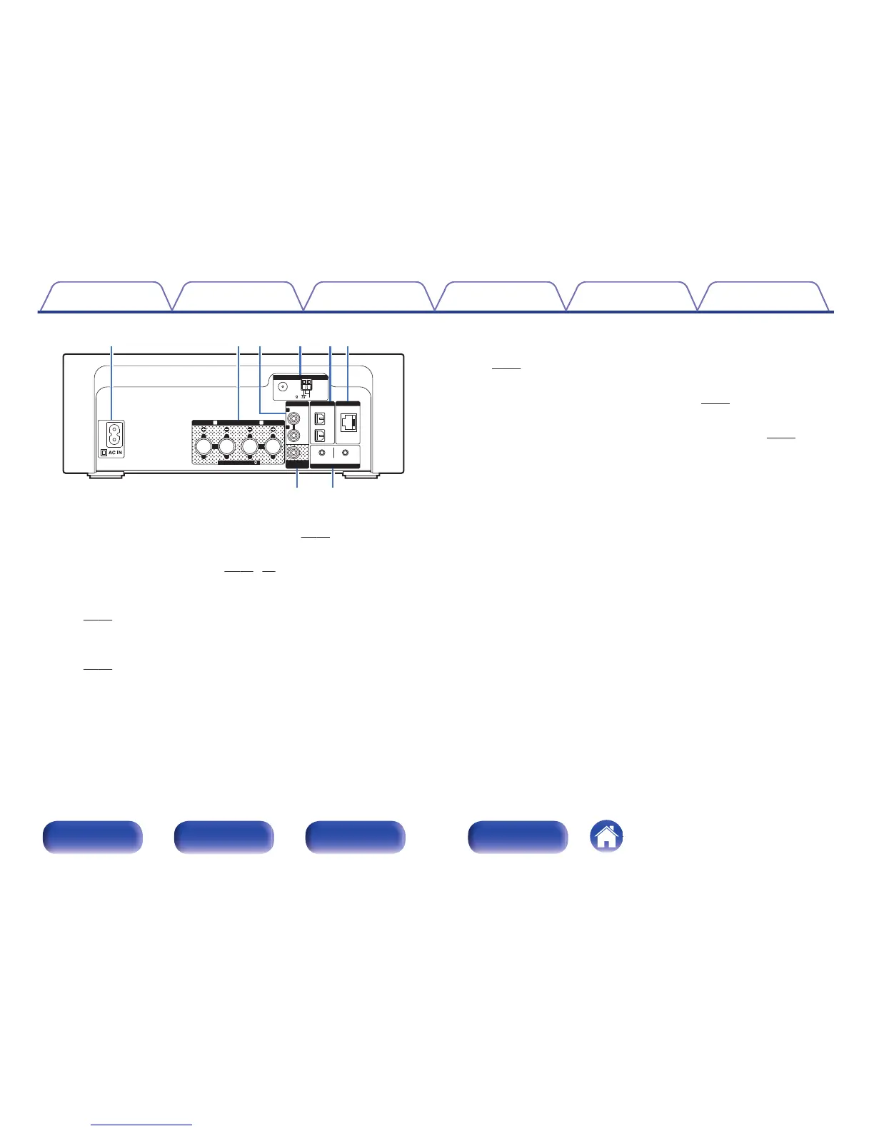
AC inlet (AC IN)
Used to connect the supplied power cord. (v
p. 29)
B
Speaker terminals (SPEAKERS)
Used to connect speakers. (v p. 18, 20)
C
ANALOG IN connectors
Used to connect devices equipped with analog audio connectors.
(v
p. 21)
D
Antenna terminals (ANTENNA)
Used to connect FM room antennas and AM loop antennas.
(v
p. 24)
E
DIGITAL IN connectors
Used to connect devices equipped with digital audio connectors.
(v p. 21)
F
NETWORK connector
Used to connect this unit to the network. (v
p. 26)
G
SW OUT connector
Used to connect a subwoofer with a built-in amplifier. (v
p. 19)
H
Wi-Fi CONNECT buttons (iOS/WPS)
Used to connect to the wireless LAN.
(See the separate “Quick Setup Guide”.)
Contents Connections Playback
Settings
Tips Appendix
13
Front/Top
panel
Rear panel
Remote control unit
Index

 Loading...