40
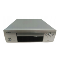
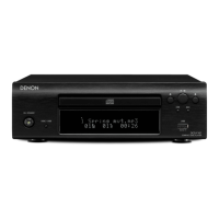
DCD-710AE
TMP92CD28AFG
Block Diagram
TMP92CD28AFG Terminal Function
Pin
No
IC Terminal name
DCD-710AE/755SE
Terminal name
I/O RST INIT STB
Pull
U/D
Port function
1 /RESET RESETTerminal I I I - PU Port only for input
(Schmitt input and PU resistance)
2 PC0/INT0 Reserved I - I - PD Port only for input (with Schmidt input)
3 PC1/INT1 Non (PD) I - I - PD Port only for input (with Schmidt input)
4 PC2/INT2/TB1IN0/
TB0IN0
SYSTEM BUSY input I - I - Port only for input (with Schmidt input)
5 PC3/INT3 STREQ input I-I - Port only for input (with Schmidt input)
6 DVCC3B Power supply (+3.3V) P P P P - Power supply (+3.3V)
7 XT1 Non (NC) I I I - - Input port
8 XT2 Non (NC) O O I - - Output port
 Loading...