GE Analytical Instruments, Inc. ©2005H Page 2 of 4 DIN 74740 Rev. A
Kit, Interconnect Board Repl., 500
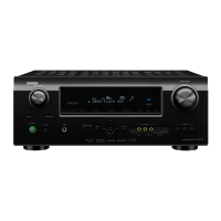
Figure 1 The 500 RL’s Electronics Boards
5.9 Remove the I/O board
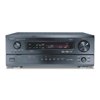
5.9.1 Disconnect the UV lamp power connector from the I/O board (see Figure 2).
Figure 2 The UV Power Connector
5.9.2 If there is wiring connected to the terminal blocks on the I/O board, remove the terminal blocks.
Grasp each terminal block firmly and pull it straight out from the connector.
5.9.3 Press down on the silver buttons on each side of the I/O board to release the locking pins (see
Figure 1).
5.9.4 Immediately in front of the pins are the board ejectors. Using your thumbs, simultaneously push
the ejectors out, toward the board guides. This will cause the board to begin to come forward.
5.9.5 Slide the board out of the guides and then out of the Analyzer.