Do you have a question about the Denon DRA-N5 and is the answer not in the manual?
Specifies the model number and type of equipment serviced.
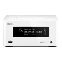
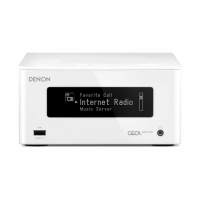
Identifies the type of equipment serviced as a network receiver.
Explains how to use the search function in Acrobat Reader for efficient navigation.
Details how to use the Ctrl+Shift+F shortcut to search for reference numbers.
Guides users on clicking connectors in schematic diagrams to jump to their targets.
Describes how to use the Sign function in Adobe Reader to add notes.
Explains how to magnify diagrams using Ctrl+Space and mouse drag.
Details steps and settings for printing magnified manual sections.
Instructions for checking leakage current before returning the set to the customer.
General cautions and instructions to be followed during servicing and inspection.
Highlights the importance of using designated parts with special safety properties.
Warns about parts indicated by a mark having critical characteristics.
Recommends leakage current and resistance checks before set return.
Provides notices regarding resistance, capacitance values, and circuit changes.
States that parts marked 'nsp' cannot be supplied.
Advises to distinguish between '1' and 'I' when ordering parts.
States parts ordered without a number cannot be supplied.
Notes parts with a '' mark are not illustrated in the exploded view.
Refers to schematic for general purpose Carbon Film Resistors.
Refers to schematic for general purpose Carbon Chip Resistors.
Warns about parts with a mark having critical characteristics.
Recommends wearing a grounding band (1 MΩ) to remove static electricity.
Advises using a conductive sheet or copper plate with grounding for the workbench.
Details specifications for the audio amplifier section.
Lists technical specifications for Wireless LAN (E2) compliance.
Lists technical specifications for Wireless LAN (E3) compliance.
Specifies clock and alarm features.
Details power supply voltage, frequency, and consumption.
Instructions for replacing the WLAN module and related procedures.
Steps for initializing the network receiver after component replacement.
Procedure for disassembling the top cover.
Procedure for disassembling the main PCB assembly.
Procedure for disassembling the front panel assembly.
Procedure for disassembling the SMPS PCB assembly.
Procedure for disassembling the amplifier PCB assembly.
Illustrates the different shooting directions for disassembly photographs.
Indicates the current step in the disassembly process.
Shows the bottom view for screw removal.
Identifies the view shown in photograph A for this step.
Indicates the disassembly sequence leading to the main PCB.
Describes the first step in disassembling the main PCB.
Describes the second step in disassembling the main PCB.
Details the disassembly sequence leading to the front panel.
Shows the bottom view for screw removal during front panel disassembly.
Describes disconnecting wires for USB, WiFi, and headphones.
Outlines the disassembly sequence for the SMPS PCB.
Instruction for removing screws during SMPS PCB disassembly.
Instruction for removing the SMPS shielding plate.
Details the disassembly sequence for the amplifier PCB.
Instruction for removing screws during amplifier PCB disassembly.
Another instruction for removing screws during amplifier PCB disassembly.
Explains how to enter special modes by pressing buttons while plugging in the power cord.
Lists cautions regarding clearing version info and protection history.
Describes the display sequence when entering Factory Reset mode.
Lists default settings for various items upon initialization.
Notes differences from factory reset (version info, protection history).
Describes the display sequence for User Reset mode.
Explains how to enter and exit the version display mode.
Step-by-step guide on how to access the version information via menus.
Describes the startup display for Product Mode 1.
Details the function and settings for cooling fan testing.
Describes the startup display for Product Mode 2.
Describes the startup display for protection history mode.
Lists error codes and coping strategies for DPMS firmware updates.
Covers preparation and error checking for firmware updates.
Details error codes related to the main microprocessor during firmware updates.
Describes firmware updating via PC using RS232C connection.
Briefly mentions MAC address rewriting for production/development.
Mentions access to development server mode for production/development.
Explains cooling fan operation based on temperature sensor readings.
Details confirmation steps after replacing the microprocessor or Flash ROM.
Explains ROM types and their software implications.
Notes the need for software updates when replacing the WLAN MODULE.
Provides instructions on how to update firmware using DPMS.
Lists system requirements for network connection for firmware updates.
Guides on checking for and performing firmware updates via DPMS.
Lists important cautions to observe during the firmware update process.
Troubleshooting steps for when the OLED display does not light up.
Checks power supply voltages for the main µ-com.
Checks the reset signal for the main µ-com.
Checks the oscillation waveform on the main board.
Checks power supply voltages specifically for the OLED.
Checks drive signals for the OLED display.
Common troubleshooting steps for no sound or noise issues.
Checks power supply voltages for the DIR AMP board.
Checks power supply voltages for the PWM controller.
Checks power supply voltages for the amplifier IC.
Checks the reset signal for the DIR AMP board.
Checks the reset signal for the PWM controller.
Checks the reset signal for the amplifier IC.
Checks the oscillation waveform on the amplifier board.
Checks the analog audio signal from the AUX input.
Checks the input signal from the DIR.
Checks the digital audio data output from the DIR.
Checks the digital audio data input for the PWM controller.
Checks the PWM audio data output for the PWM controller.
Checks the audio data output from the AMP to the speaker.
Checks power supply voltages for the optical input IC.
Checks the digital audio data from the optical input IC.
Checks power supply voltages for the network interface.
Checks power supply voltages for the USB interface.
Checks power supply voltages for the iPod Dock.
Checks power supply voltages for the CR870 unit.
Checks the reset signal for the Ethernet board (CR870).
Checks digital audio data for the CODEC.
Illustrates the block diagram of the Key board.
Illustrates the block diagram of the Display board.
Illustrates the block diagram of the Main board.
Illustrates the block diagram of the Ethernet and USB board.
Shows the block diagram of the switched-mode power supply.
Shows the component side of the Audio printed wiring board.
Shows the foil side of the Audio printed wiring board.
Shows the component side of the Front printed wiring board.
Shows the foil side of the Front printed wiring board.
Shows the component side of the Headphone printed wiring board.
Shows the foil side of the Headphone printed wiring board.
Shows the component side of the USB printed wiring board.
Shows the foil side of the USB printed wiring board.
Part 1 of the main unit schematic, showing primary components.
Part 2 of the main unit schematic, showing secondary components.
Schematic diagram for the iPod unit.
Continues the main unit schematic, showing secondary components.
Schematic diagram for the iPod unit.
Schematic diagram for the audio unit.
Schematic diagram for the headphone unit.
Schematic diagram for the USB unit.
Schematic diagram for the front unit.
Schematic diagram for the key unit.
Schematic diagram for the CNT2 unit.
Schematic diagram for the CNT1 unit.
Schematic diagram for the CNT3 unit.
Schematic diagram for the SMPS unit.
Lists IC components, focusing on detailed drawings in schematic diagrams.
Pin description and functions for IC403, a Renesas microcontroller.
Pin description and functions for the display controller CP661.
| Remotely operated | Yes |
|---|---|
| Security algorithms | WPS |
| Supported radio bands | FM, VHF |
| Built-in storage media | No |
| Audio formats supported | AAC, FLAC, MP3, WAV, WMA |
| Internet radio services supported | iDevice, iTunes |
| Network streaming services supported | - |
| Product color | White |
| Wi-Fi standards | 802.11b, 802.11g |
| Digital audio optical out | 1 |
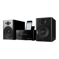
| Apple docking compatibility | iPhone, iPod |
| AC input voltage | 230 V |
| AC input frequency | 50 Hz |
| Power consumption (typical) | 50 W |
| Depth | 234 mm |
|---|---|
| Width | 120 mm |
| Height | 90 mm |
| Weight | 2300 g |