EasyManuals Logo

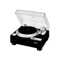
Denon DP-59L Service Manual

Denon DP-59L
18 pages
To Next Page IconTo Next Page
To Previous Page IconTo Previous Page
Page #6 background imageLoading...
Page #6 background image
EXPLANATION
OF
THE
MICROPROCESSOR
@
Motor
Control
IC
.....
IR3TO5
(at
standard
re-
5.
Power
source
input
volution
of
33
rpm)
The
numbers
on
the
left
hand
side
indicates
the
terminal
Vec:
5V
+0.5V
number.
6.
FGI
bypass
terminal
1.
Stop
output
E6=%
Vcc
during
stop
control:
OV
during
start:
open
7.
FGI
lowpass
terminal
2.
Lockindicator
ees
during
lock
.....
(LED
lit
dimly)
fo)
Re
eh
a
ea
=
1.2~1.5V
69HZ
1/2
Vee
ey
|
|
T-
4v
8.
FGI
output
1.8mS
SOO
csietdeiceamtes
(LED
iit)
=1.2~1.5V
during
transition
....
(LED
flashes)
1/2
Vec
0.45S
2.2HZ
9.
|
| |
ji
=4V
The
gain
set
element
is
connected.
FGI
inverse
input
E9=%
Vcc
3.
0.22us
(0%)
10.
FGI
non-inverse
input
(0%)
10mVpp
~
100mVpp
|
0.22us
|
E10=%
Vee
3V
11.
-FG
Il
non-inverse
input
OV
:
|
10mVpp
~
100mVpp
Frequency
will
vary
by
changing
turntable
revolution
E113
%
Vee
within
the
range
of
+9.9%.
4.
rpm
selector
P
12.
FG
Il
inverse
input
H:
45
rpm
|
L:
33rpm
The
gain
set
element
is
connected,
E12=%
Vee

Questions and Answers:

Question and Answer IconNeed help?

Do you have a question about the Denon DP-59L and is the answer not in the manual?

Denon DP-59L Specifications

General IconGeneral
Drive SystemDirect Drive
MotorAC Servo Motor
Wow and Flutter0.008% WRMS
Platter Size300 mm
Effective Tonearm Length244 mm
Speed33 1/3, 45 rpm
PlatterDie-cast aluminum
Tonearm TypeStatic balance type (interchangeable)

Related product manuals