EasyManua.ls Logo

Denon DP-500M Service Manual

Denon DP-500M
28 pages
To Next Page IconTo Next Page
Page #1 background imageLoading...
Page #1 background image
SERVICE MANUAL
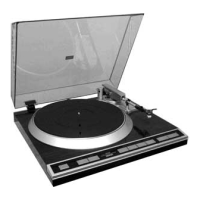
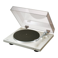
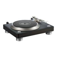
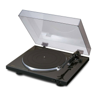
DIRECT DRIVE TURN TABLE SYSTEM
MODEL DP-500M
Denon Brand Company, D&M Holdings Inc.
X0193 V.05 DE/CDM 0712
Some illustrations using in this service manual are
slightly different from the actual set.
Please use this service manual with referring to the
operating instructions without fail.
For purposes of improvement, specifications and
design are subject to change without notice.
本文中に使用しているイラストは、説明の都合上現物
と多少異なる場合があります。
修理の際は、必ず取扱説明書を参照の上、作業を行っ
てください。
サービスをおこなう前に、このサービスマニュアルを
必ずお読みください。本機は、火災、感電、けがなど
に対する安全性を確保するために、さまざまな配慮を
おこなっており、また法的には「電気用品安全法」に
もとづき、所定の許可を得て製造されております。
従ってサービスをおこなう際は、これらの安全性が維
持されるよう、このサービスマニュアルに記載されて
いる注意事項を必ずお守りください。
本機の仕様は性能改良のため、予告なく変更すること
があります。
補修用性能部品の保有期間は、製造打切後8年です。
注 意
For U.S.A. model
Ver. 5
Please refer to the
MODIFICATION NOTICE.

Other manuals for Denon DP-500M

Questions and Answers:

Denon DP-500M Specifications

General IconGeneral
Drive SystemDirect Drive
Speeds33 1/3, 45 RPM
Power Consumption10 W
CartridgeNot included
PlatterAluminum
Overhang15 mm
Signal to Noise Ratio70 dB
Power SupplyAC 100 V, 50/60 Hz
Frequency Response20Hz ~ 20kHz

Summary

General Information and Safety Warnings

Safety Precautions

Service Safety Procedures

Covers checks, handling, and inspections for safe servicing.

Important Safety Parts

Part Identification and Usage

Identifies critical parts marked with ▲ and emphasizes using designated replacements.

Disassembly Steps

Platter and Bottom Base Removal

Instructions for removing the platter and bottom base assembly.

PWB and Motor Assembly Removal

Steps to remove the main PWB, tone arm, D.D. motor, and transformer assemblies.

Button Assembly and Disassembly

Procedures for removing and disassembling the button assembly.

Block Diagram

System Overview

Illustrates the functional blocks and key integrated circuits in the system.

Adjustment Procedures

Wow and Flutter Adjustment

Guide for adjusting wow and flutter using R134 for speed accuracy.

Semiconductor Components

IC Descriptions and Pinouts

Details pin configurations for IC303 (MAX003) and IC304 (W27E512).

Component Diagrams and Descriptions

NJM-2147D IC Description

Provides the schematic and pinout for the NJM-2147D integrated circuit.

HEDS9700F51 IC Description

Illustrates the internal structure of the HEDS9700F51 optical encoder.

Electronic Component Identification

Transistor and Diode Descriptions

Presents pinouts and basic diagrams for US1881, DTC124TS, 2SB1340, and 2SD1889.

Printed Wiring Board Layouts (Part 1)

Main PWB Unit Layout

Shows foil and component sides of the main printed circuit board.

Other PWB Units Layout

Displays layouts for Output, 33/45, AC, and Start/Stop PCBs.

Printed Wiring Board Layouts (Part 2)

D.D. Motor PWB Unit Layout

Illustrates the component and foil sides of the D.D. Motor PCB.

Parts List Usage Notes

Resistor and Capacitor Conventions

Explains how to interpret resistor and capacitor part numbers and values.

Parts List - Main PWB Unit

Semiconductors, Resistors, Capacitors

Lists semiconductor devices, resistors, and capacitors for the main PWB.

Parts List - DC, 33/45 & Start/Stop PWB Units

Semiconductors and Other Parts

Lists components for DC, 33/45, and Start/Stop PCBs, including semiconductors and connectors.

Parts List - Output & Power PWB Units

Capacitors and Other Parts

Lists capacitors and various other parts for output and power PCBs.

Parts List - D.D. Motor PWB Unit

Semiconductors and Fuses

Lists semiconductor components and fuses for the D.D. motor PCB.

Parts List - Resistors for D.D. Motor PWB

Resistor Details

Lists various resistors used in the D.D. Motor PWB.

Parts List - Capacitors (C101-C141, C901-C908)

Capacitor Details

Provides detailed listings for numerous capacitor components.

Parts List - Other Components

Capacitors and Miscellaneous Parts

Lists remaining capacitors and miscellaneous parts like beads and screws.

Exploded View and Component Identification

Assembly Diagram and Part Numbers

Visual representation of assemblies with corresponding reference numbers for parts.

Exploded View Parts List - Chassis and Assemblies

Major Assemblies and Chassis Components

Lists parts for chassis, base, platter, buttons, motor, transformer, and PWB assemblies.

Exploded View Parts List - Accessories

Labels, Cords, and Accessories

Lists various labels, power cords, and accessories included with the product.

Maintenance - Points of Greasing

Greasing Locations and Specifications

Details specific points requiring grease and the type/amount to use.

Packing and Accessories List

Packaging Materials and Components

Lists items used for packaging the product and included accessories.

Connections Diagram

Printed Circuit Board Interconnections

Illustrates how the various PWB units are connected to each other.

Schematic Diagram Conventions

Symbol and Unit Explanations

Clarifies symbols, resistance, capacitance, voltage, and current notations used in schematics.

Schematic Diagrams (Part 1)

D.D. Motor Unit Schematic

Circuit diagram for the direct drive motor control section.

AC Power Unit Schematic

Circuit diagram for the AC power supply section.

DC Unit Schematic

Circuit diagram for the DC power regulation section.

Schematic Diagrams (Part 2)

Main, 33/45, Start/Stop, Output Units Schematics

Circuit diagrams for main, speed control, start/stop, and output units.

Related product manuals