Do you have a question about the Denon DP-59L and is the answer not in the manual?
Electronically damped resonance for optimized stereo imaging and reduced noise.
Dual construction arm tube reduces resonance, improving tracing ability and clarity.
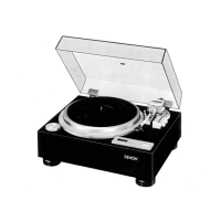
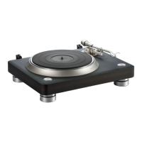
Thick platter minimizes vibrations for clear sound reproduction and acoustic characteristics.
Utilizes PLL method for precise speed control, maintaining accuracy within +/-9.9%.
Features AC servo motor and quartz lock for low wow/flutter and high S/N ratio.
Automatically lifts stylus and stops rotation at record end to prevent stylus wear.
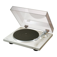
Features a mirror-finish surface and improved insulators to prevent howling.
Allows quick cartridge matching via standard 4-pin connectors.
Controls power supply activation and arm lift movement.
Manages turntable rotation and arm lifter engagement.
Indicates stable turntable speed lock and transitional states.
Allows switching between 33-1/3 rpm and 45 rpm speeds.
Controls the vertical movement of the tonearm.
Provides precise speed adjustment via the quartz-lock system.
Compensates for inward stylus pull during record playback.
Adjusts tonearm damping based on stylus force settings.
Used to achieve zero balance for the tonearm.
Secures the tonearm in place, disengaging the lock when moved.
Explains IR3T05 IC functions for motor control, stop output, and lock indicator.
Details speed indication, rpm selector inputs, and associated signals.
Describes various FG, PD, and F/V output terminals and their signal characteristics.
Details FG II output, F/V output, and F/V triangular wave signals.
Explains PD triangular wave, sample pulse monitor, and PD hold terminals.
Describes lock detector time set, direction detector output, and revolution detector.
Explains LCD segment outputs and rpm change inputs for speed control.
Details UP, DOWN, and NORMAL key inputs for speed adjustment.
Describes crystal inputs for 4.5MHz oscillation and reference frequency output.
Explains voltage controlled oscillator input and power supply voltage.
Details L.P.F. output for ripple signal and L.P.F. input for VCO control.
Explains phase difference detection output and GND terminal.
Describes TEST terminal, ACL state, and LCD segment outputs.
Ensures proper perpendicularity of the detection head to the turntable surface.
Adjusts VR1 and VR2 for correct speed lock indication at 33 and 45 RPM.
Adjusts VR3 for zero offset voltage in the horizontal amplifier.
Adjusts VR4 for zero offset voltage in the lifter amplifier.
Adjusts the cam for correct end-of-record detection position.
| Drive System | Direct Drive |
|---|---|
| Motor | AC Servo Motor |
| Wow and Flutter | 0.008% WRMS |
| Platter Size | 300 mm |
| Effective Tonearm Length | 244 mm |
| Speed | 33 1/3, 45 rpm |
| Platter | Die-cast aluminum |
| Tonearm Type | Static balance type (interchangeable) |