EasyManua.ls Logo

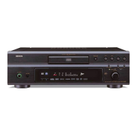
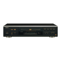
Denon DVD-3930 Service Manual

Denon DVD-3930
176 pages
To Next Page IconTo Next Page
Page #1 background imageLoading...
Page #1 background image
SERVICE MANUAL
MODEL
DVD-3930/3930CI
DVD AUDIO-VIDEO / SUPER AUDIO CD PLAYER
For U.S.A., Canada, Europe,
& Japan model
X0274 V.01 DE/CDM 0607
Some illustrations using in this service manual are
slightly different from the actual set.
Please use this service manual with referring to the
operating instructions without fail.
For purposes of improvement, specifications and
design are subject to change without notice.
本文中に使用しているイラストは、説明の都合上現物
と多少異なる場合があります。
修理の際は、必ず取扱説明書を参照の上、作業を行っ
てください。
サービスをおこなう前に、このサービスマニュアルを
必ずお読みください。本機は、火災、感電、けがなど
に対する安全性を確保するために、さまざまな配慮を
おこなっており、また法的には「電気用品安全法」に
もとづき、所定の許可を得て製造されております。
従ってサービスをおこなう際は、これらの安全性が維
持されるよう、このサービスマニュアルに記載されて
いる注意事項を必ずお守りください。
本機の仕様は性能改良のため、予告なく変更すること
があります。
補修用性能部品の保有期間は、製造打切後8年です。
注 意
TOKYO, JAPAN
Denon Brand Company, D&M Holdings Inc.
Ver. 1

Other manuals for Denon DVD-3930

Questions and Answers:

Denon DVD-3930 Specifications

General IconGeneral
Audio D/A Converter192 kHz/24-bit
Progressive ScanYes
HDMI OutputYes
Dolby Digital DecodingYes
DTS DecodingYes
Disc TypesDVD-Video, DVD-Audio, CD
Video OutputComposite, S-Video, Component
Audio OutputCoaxial, Optical
UpscalingUp to 1080p

Summary

SERVICE MANUAL

注 意 (CAUTION)

Important safety precautions before performing service.

SAFETY PRECAUTIONS

LEAKAGE CURRENT CHECK

Check leakage current or line to chassis resistance before returning unit.

LASER RADIATION

Do not stare into beam or view directly with optical instruments.

CAUTION

Points to heed during servicing and inspection.

DISASSEMBLY

Disassembly and abandonment

Procedures for disassembling the unit and abandoning parts.

1. Top cover & Inner cover

1.1. トップカバー (Top cover)

Procedure for removing the top cover.

4. Power P.W.B. ass'y etc.

4.1. 電源基板 ass'y (Power P.W.B. ass'y)

Steps to remove the power supply board assembly.

DIAGNOSTICS OF OPTICAL PICKUP AND REPLACING TRAVERSE UNIT

1. Iop checked Method

1.1. DVD laser current check

Procedure to check DVD laser current.

SERVICE MODE

1. Aging Mode

Procedure for entering and performing the aging mode.

4. Test mode

4. テストモード (4. Test mode)

Instructions for entering and selecting modes in the test mode.

(7) Test mode detailed table

Table 1: Servo adjustment value display mode details

Detailed table for servo adjustment value display modes.

TROUBLE SHOOTING

1. GU-3750-2 (DIGITAL POWER UNIT)

Troubleshooting steps for the Digital Power Unit (GU-3750-2).

ELECTRICAL ADJUSTMENT FOR VIDEO

1. SETTING

Initial setup procedures for video adjustment.

BLOCK DIAGRAM

SEMICONDUCTORS

1. IC’s

List and pin functions of major integrated circuits used.

PRINTED WIRING BOARDS

GU-3749 MAIN/A. VIDEO P.W.B. UNIT

Component layout diagram for the Main/Video PWB Unit.

NOTE FOR PARTS LIST

Resistors

Explanation of resistor codes and markings.

PARTS LIST OF P.W.B. UNIT (for E3 model)

SEMICONDUCTORS GROUP

List of semiconductor components on the PWB.

EXPLODED VIEW

Parts marked with this symbol have critical characteristics.

Warning about parts with critical characteristics.

WIRING DIAGRAM

MEASURING METHOD AND WAVEFORMS

NOTES

Notes regarding measurement methods and waveforms.

NOTE FOR SCHEMATIC DIAGRAM

WARNING:

Warning about critical parts in schematics.

SCHEMATIC DIAGRAMS (1/20)

SCHEMATIC DIAGRAMS (1/20)

Schematic diagram of the Main Unit (Part 1 of 20).

PRINTING THE SERVICE MANUAL

TO PRINT FULL SIZE SCHEMATIC DIAGRAMS

Instructions for printing full-size schematic diagrams.

Related product manuals