29
Front Panel
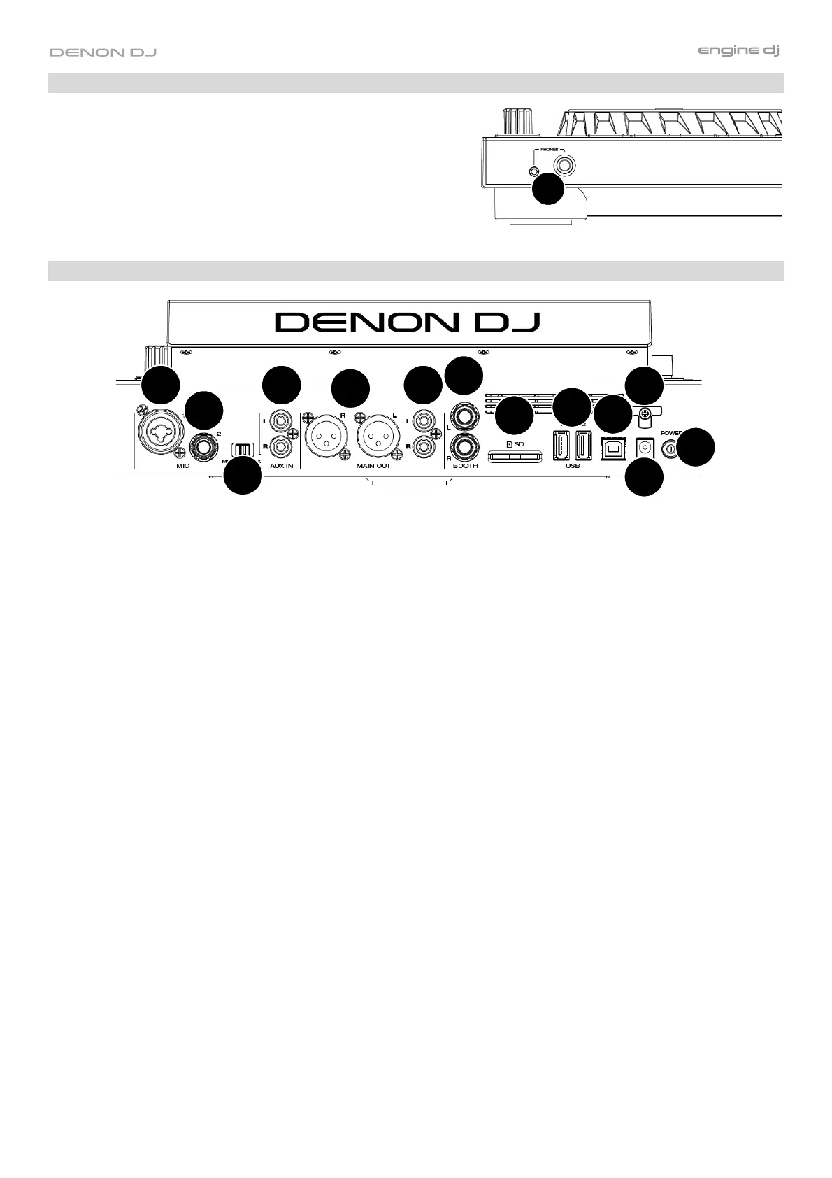
1. Headphones (1/4”, 1/8”) (6.35 mm, 3.5 mm): Connect your
1/4” or 1/8” (6.35 mm or 3.5 mm) headphones to this output
for cueing and mix monitoring. The headphone volume is
controlled using the Headphones Level knob.
Rear Panel
2
1
4
5
6
7
3
10
9
12
11
13
8
1. Power Button: Press this button to power SC LIVE 4 on. Power on SC LIVE 4 only after you have connected all
your input devices and before you power on your amplifiers and loudspeakers.
To power off SC LIVE 4, press this button and follow the prompts on the touchscreen. Power off your amplifiers
and loudspeakers before powering off SC LIVE 4.
2. Power Input: Use the included power adapter to power the unit.
3. Power Cable Support: Wrap the power cable here for added support.
4. USB-B Port: Use a standard USB cable (included) to connect this USB port to an available USB port on your
computer.
5. USB-A Ports 1–2: Connect standard USB drives to these USB ports. When you select a USB drive as a source,
you can use the touchscreen to select and load tracks from your USB drive.
6. SD Card: Insert a standard SD card to this slot. When you select that SD card as a source, you can use the
display to select and load tracks on your SD card.
7. Booth Outputs (1/4” / 6.35 mm): Use standard 1/4” (6.35 mm) cables to connect these outputs to booth
monitors or a booth amplifier system. Use the Speaker/Booth Level knob on the top panel to control the volume
level.
8. Main Outputs (RCA, unbalanced): Use standard RCA cables to connect these outputs to loudspeakers or an
amplifier system. Use the Main Volume knob on the top panel to control the volume level.
9. Main Outputs (XLR, balanced): Use standard XLR cables to connect these outputs to loudspeakers or an
amplifier system. Use the Main Volume knob on the top panel to control the volume level.
10. Aux Input (RCA, unbalanced): Use standard RCA cables to connect these line-level inputs to an external audio
source. Set the Mic 2/Aux switch to Aux and then use the Aux/Mic 2 Level knob on the top panel to control the
volume level.
11. Mic 2/Aux: Use this switch to select whether the Mic 2 Input or Aux Input is active.
12. Microphone 1 Input (XLR): Use a standard XLR cable (not included) to connect a standard dynamic microphone
to this input. Use the Mic 1 Level knob on the top panel to control the volume level.
13. Microphone 2 Input (1/4” / 6.35 mm): Use a standard 1/4” (6.35 mm) cable (not included) to connect a standard
dynamic microphone to this input. Set the Mic 2/Aux switch to Mic 2 and then use the Aux/Mic 2 Level knob on
the top panel to control the volume level.
1
 Loading...