59
S-102
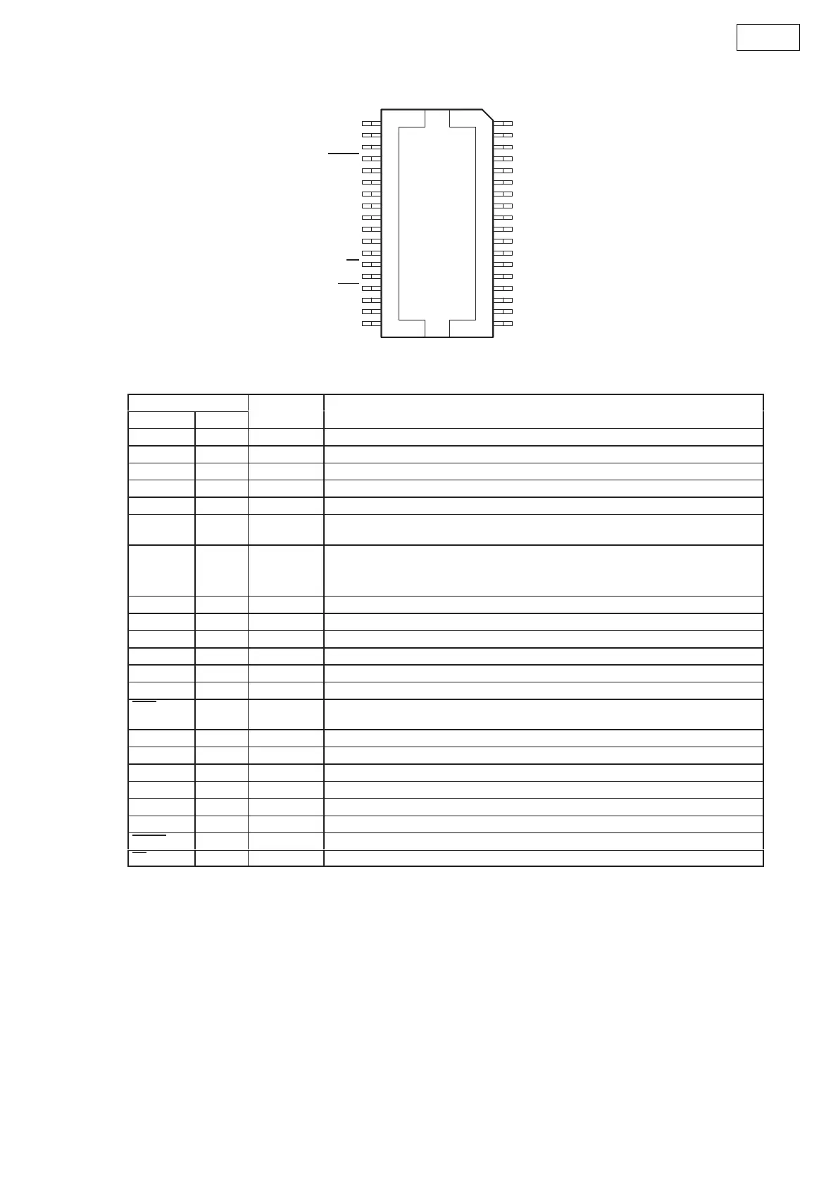
TAS5121DKD (IC207: 1U-3811)
1
2
3
4
5
6
7
8
9
10
11
12
13
14
15
16
17
18
36
35
34
33
32
31
30
29
28
27
26
25
24
23
22
21
20
19
GND
PWM_BP
GND
RESET
REG_RTN
GVDD
M3
DREG
DGND
M1
M2
DVDD
SD
DGND
OTW
GND
PWM_AP
GND
GVDD_B
GVDD_B
GND
BST_B
PVDD_B
PVDD_B
OUT_B
OUT_B
GND
GND
OUT_A
OUT_A
PVDD_A
PVDD_A
BST_A
GND
GVDD_
A
GVDD_A
Terminal Functions
TERMINAL
NAME DKD
FUNCTION
DESCRIPTION
BST_A 22 P High side bootstrap supply (BST), external resistor and capacitor to OUT_A required
BST_B 33 P High side bootstrap supply (BST), external resistor and capacitor to OUT_B required
DGND 9, 14 P I/O reference ground
DREG 8 P Digital supply voltage regulator decoupling pin, 1 μFcapacitor connected to DREG_RTN
DREG_RTN 5 P Decoupling return pin
DVDD 12 P I/O reference supply input: 100 Ω to DREG, decoupled to GND, 0.1 μF capacitor connected to
GND
GND 1, 3, 16,
18, 21,
27, 28,
34
P Power ground, connected to system GND
GVDD 6 P Local GVDD decoupling \pin
GVDD_A 19, 20 P Gate drive input voltage
GVDD_B 35, 36 P Gate drive input voltage
M1 10 I Protection mode selection pin, connect to GND
M2 11 I Protection mode selection pin, connect to DREG
M3 7 I Output mode selection pin; connect to GND
OTW 15 O Overtemperature warning output, open drain with internal pullup, active-low when temperature
exceeds 115°C
OUT_A 25, 26 O Output, half-bridge A
OUT_B 29, 30 O Output, half-bridge B
PVDD_A 23, 24 P Power supply input for half-bridge A
PVDD_B 31, 32 P Power supply input for half-bridge B
PWM_AP 17 I PWM input signal, half-bridge A
PWM_BP 2 I PWM input signal, half-bridge B
RESET 4 I Reset signal, active low
SD 13 O Shutdown signal for half-bridges A and B (open drain with internal pullup)
(1)
I = input, O = Output, P = Power
 Loading...