10
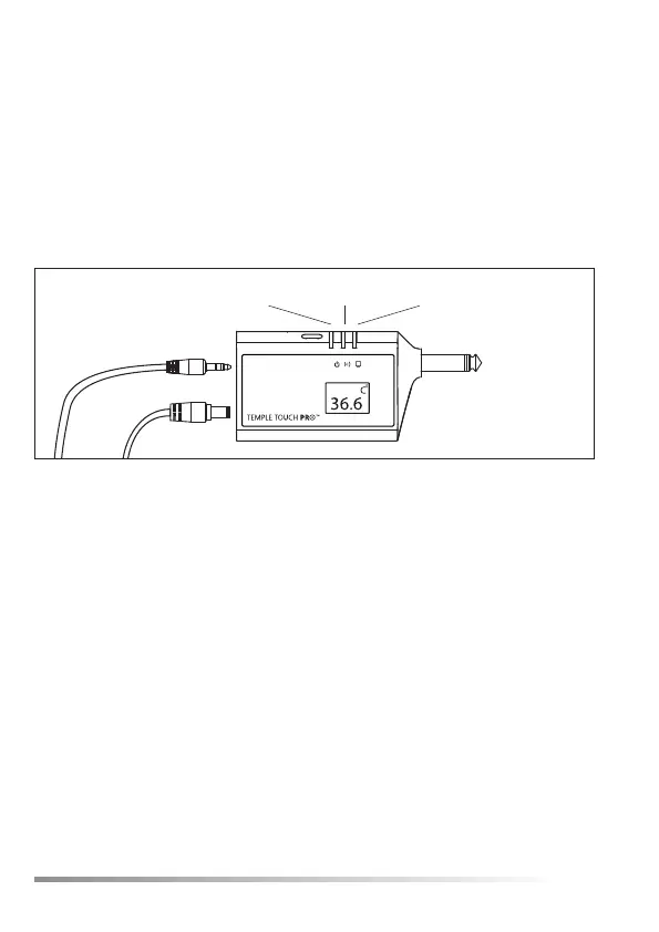
The TTP™ Monitor Connecng Unit (MCU)
The MCU receives data from the SU through the SCU and
transmits the informaon related to the paent’s core
temperature to the VSM. The MCU is connected to the power
supply via Inlet B.
The TTP™ system is designed to display operaon feedback
throughtheMCULEDsandtheSCULEDlocatedontheSCU.
Figure4
Inlet A
Power Connecvity VSM
Inlet B
11
LED name Symbol Color Funconality Locaon
POWER Yellow Turns ON when the
MCU is properly
connected to a power
supply.
MCU
CONNECTIVITY Green BlinkswhentheMCU
is properly connected
to the SCU.
MCU
VSM Green Turns ON when the
MCU is properly
connected to the VSM
andfullyfunconing.
MCU
SCU Green Turns ON when
the SU is properly
connected to the
SCU.
SCU
TableA.1-LEDIndicaonDescripon:
10
The TTP™ Monitor Connecng Unit (MCU)
The MCU receives data from the SU through the SCU and
transmits the informaon related to the paent’s core
temperature to the VSM. The MCU is connected to the power
supply via Inlet B.
The TTP™ system is designed to display operaon feedback
throughtheMCULEDsandtheSCULEDlocatedontheSCU.
Figure4
Inlet A
Power Connecvity VSM
Inlet B
11
LED name Symbol Color Funconality Locaon
POWER Yellow Turns ON when the
MCU is properly
connected to a power
supply.
MCU
CONNECTIVITY Green BlinkswhentheMCU
is properly connected
to the SCU.
MCU
VSM Green Turns ON when the
MCU is properly
connected to the VSM
andfullyfunconing.
MCU
SCU Green Turns ON when
the SU is properly
connected to the
SCU.
SCU
TableA.1-LEDIndicaonDescripon: