www.desatech.com
108321-01B 3
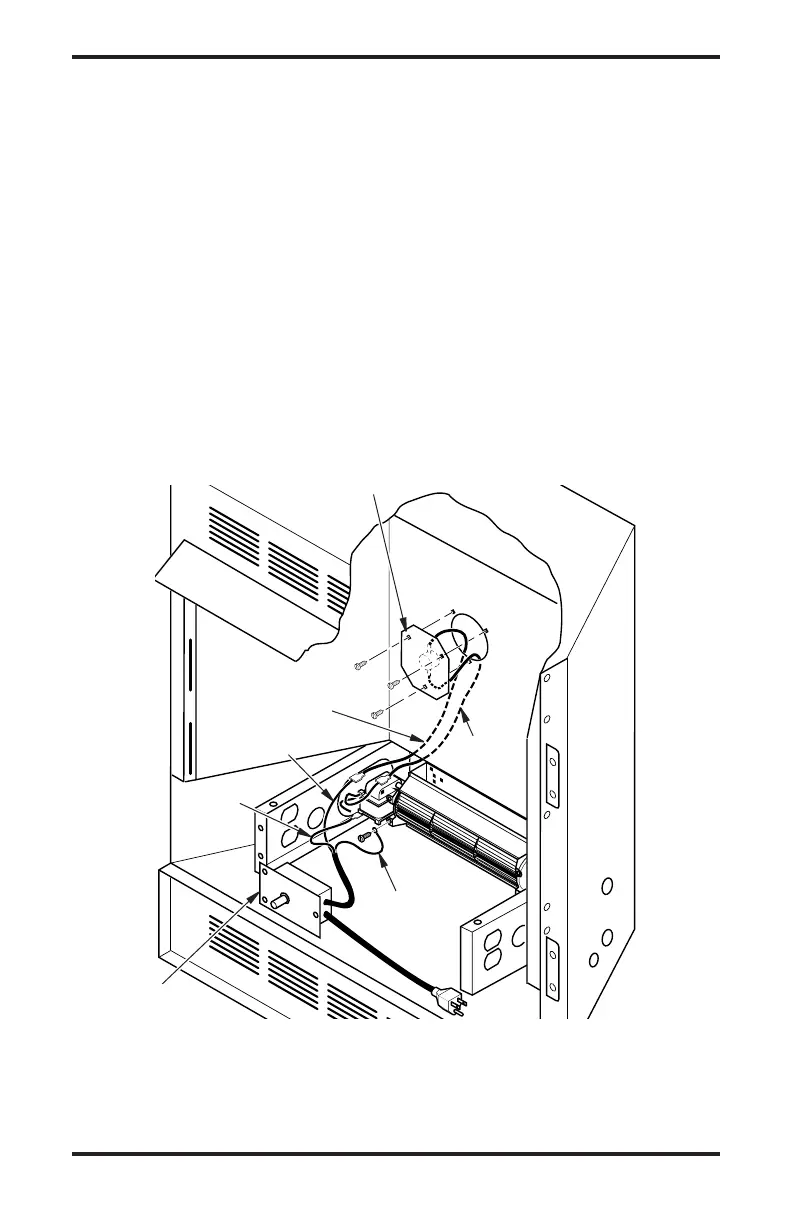
4. Remove the three screws (do not discard) and
cover plate from center of rebox wrapper rear
wall. Discard this cover plate (see Figure 2).
5. Mount the supplied thermostatic switch and
cover assembly into rebox wrapper wall. Do
this by feeding terminal ends of wire harness
into the hole. Allow wires to fall to bottom of
rebox cavity (see Figure 2).
6. Using three screws from step 7, attach switch
and cover assembly to rebox wrapper rear
wall. Tighten screws rmly (see Figure 2).
INSTALLING BLOWER
ACCESSORY IN A 32"
FIREPLACE SYSTEM
Continued
Figure 2 - Installing Switch and Cover Assembly, and Speed Control
Thermostatic Switch
and Cover Assembly
Red
Wire
Blue
Wire
Black Wire
Green Wire
White
Wire
Speed Control
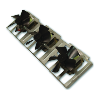
7. Place the blower against lower rear wall
of rebox outer wrapper with the exhaust
port directed upward. Align the holes in top
mounting tabs of blower with holes in wall of
wrapper (see Figure 3, page 4). Using two #8
screws provided, mount blower and tighten
screws rmly.
8. Firmly attach red wire from the thermostatic
switch and cover assembly to either of the
terminals on the blower motor (see Figure 2).
9. Firmly attach black wire from speed control
cord to blue wire from thermostatic switch
and cover assembly (see Figure 2).
10. Firmly attach white wire from speed control
cord to remaining terminal on blower motor
(see Figure 2).
11. Using screw provided, attach green ground
wire from speed control cord to blower hous-
ing.Tighten screw securely (see Figure 2).
 Loading...