Safety Information
06/2021 7 / 268
Tool extension cables
Length (m) Length (ft) Part number
8 26.2 6159175810
16 52.5 6159175840
32 105 6159175870
Mounting plates
Mounting plates are not supplied.
Refer to the following guideline drawing numbers available
at https://www.desouttertools.com/resource-centre
.
Model Drawing number
Clamping screw
size
EFD43-8 6159701380 M6 x 20
EFD43-15 6159701380 M6 x 20
EFD43-30 6159701380 M6 x 20
EFD43-45 6159701380 M6 x 20
EFD51-70 6159701390 M8 x 25
EFD51-135 6159701390 M8 x 25
EFD60-175 6159701390 M8 x 25
EFD60-250 6159701390 M8 x 25
EFD80-330 6155482910 M8 x 25
EFD80-450 6155482910 M8 x 25
EFD80-680 6155482910 M8 x 25
EFD80-950 6155482910 M8 x 25
EFDO24-20 6159702760 M6 x 20
EFDO30-80 6159702770 M6 x 20
EFDO40-180 6159702780 M8 x 25
EFDO54-450 6159702790 M8 x 25
Controller range
Only below Multi system can be used to power and drive this
product.
CVI3 Vision 6159326910
CVI3 Vision eSTOP 6159326940
TWINCVI3 6159326970
TWINCVI3 eSTOP 6159326980
CVI3 Function 6159326900
CVI3 Function eSTOP 6159326930
Safety instructions for machine manufacturer
Desoutter should not be held responsible for any injury, acci-
dent or damage which may be the consequence of an incor-
rect installation, modification or start-up, or a use out of the
intended use of Desoutter products, by the customer or a
third party.
Operator protection
This product is aimed at being integrated as a component in a
machine.
It is not a standalone nor a hand held tool, usable as it is.
It is under the responsibility of machine manufacturer to
make sure that:
• Product is properly surrounded by guards to prevent
from any contact at purpose or unintentionally on poten-
tial hot areas on this product.
Example of guard:
• If machine start requires operator to operate continu-
ously a trigger, the Quick Stop function of the controller
is properly connected to this trigger, in addition to the
start device (digital input or network)
Refer to the product information provided with the con-
troller unit to get further details on the Quick Stop func-
tion wiring and set up.
Tool cable installation
The tool cable should be placed to avoid a prolonged contact
with the motor which is the hottest part of the tool.
Although the tool has a thermal protection which switches
off the operation when it has reached a too high temperature,
it is the responsibility of the user to configure the tool to op-
erate within the established maximum temperatures.
The integration of cables on the application must prevent a
continuous contact of the spindle cable from the spindle mo-
tor capable to generate high temperatures.
The integration must respect the recommendations provided
with the cables (included guideline 6159923380).
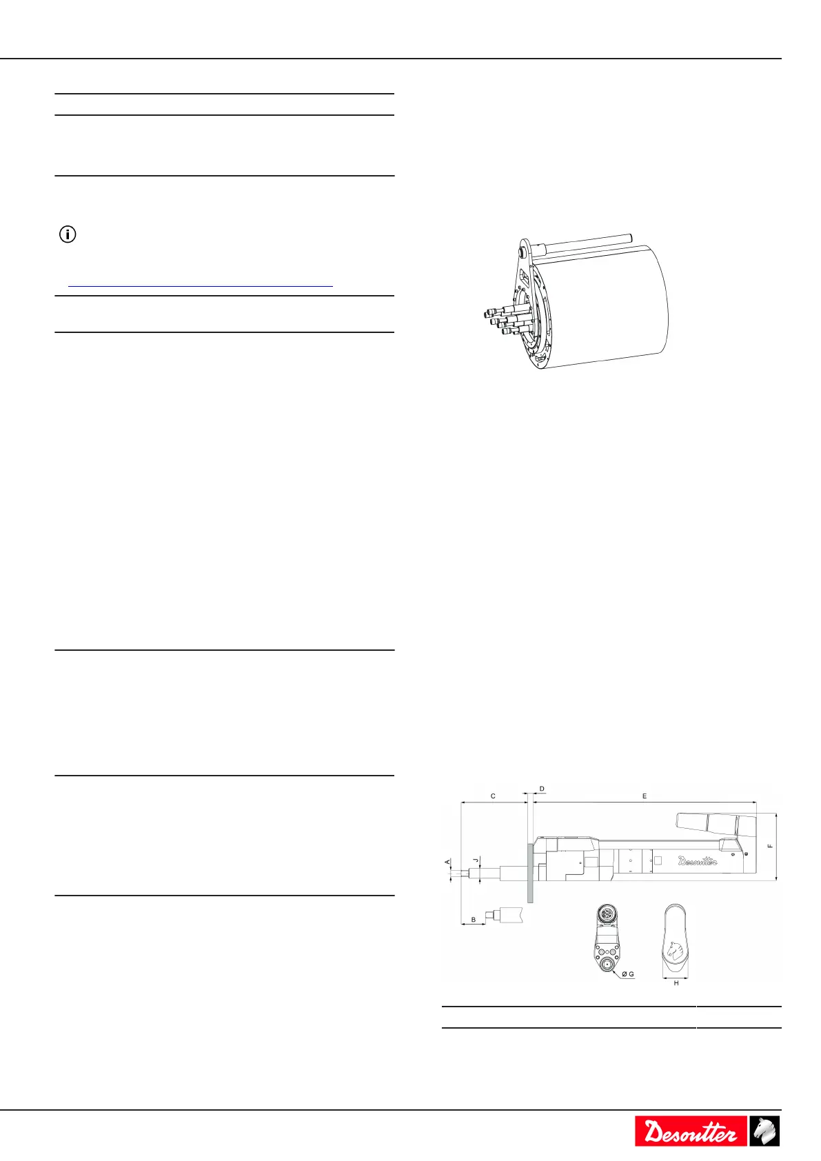
Installation
Dimensions (mm)
Model A B C
EFD43-8 9.5 50 76
EFD43-15 9.5 50 76