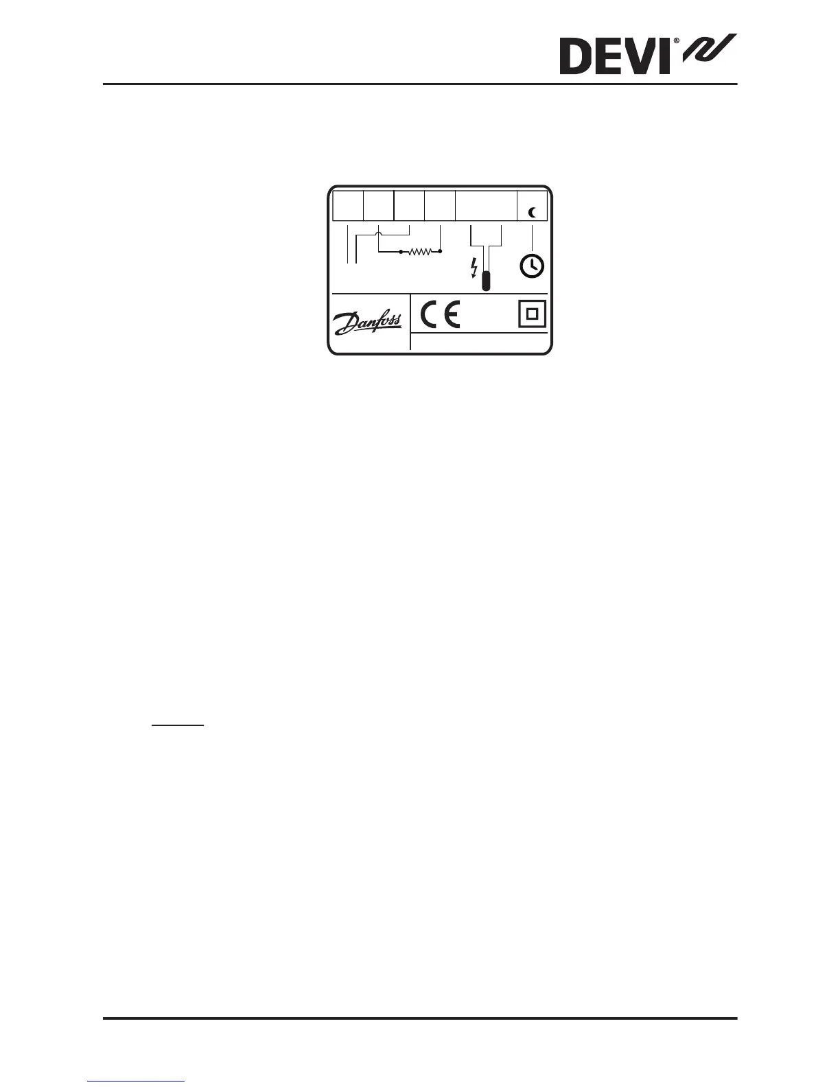
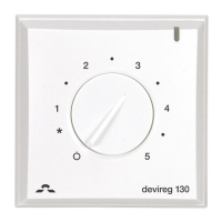
By connecting an external timer to the terminal
marked by a moon symbol (and by using for example
the same phase as for the mains power supply), the
thermostat can be set to reduce the temperature by
5ºC during specified periods.
The screen of the heating cable must be connected to
the earth conductor of the power supply cable by us-
ing a separate connector.
Note: Always install the floor sensor in a conduit in the
floor.
DEVIreg™ 530
Installation Guide 9