SB-6-156-O Page 5
Float Cover
Bottom Piece
Figure 5
3. Slide float off float guide (See Figure
6).
4. Using a knife edge, carefully pry off
float cap (See Figure 7).
Pry apart with knife edge.
5. Clean inside of float. Remove
all traces
of water or dirt.
6. Insure rubber seal is in place in the
center of the float stem (See Figure 8).
If the seal comes out, press it back in
place in the recess of the stem.
NOTE
The automatic drain includes a
float. If water gets into the float,
the automatic drain may not
function properly. Under normal
conditions, water will not enter
the float. However, water can get
in the float if the filter bowl is
washed with the drain installed
or if air line contamination causes
the drain mechanism to stick.
You can confirm the automatic drain is not
operating if the water level in the plastic
bowl is higher than the top of the auto-
matic drain.
To remove water from the float, follow
these instructions. Be careful not to lose or
damage any internal parts of the automatic
drain (replacement parts are not available
- complete drain replacement will be nec-
essary).
1. Remove automatic drain from plastic
bowl by loosening plastic retaining
nut. Keep retaining nut and o-ring for
reassembly later.
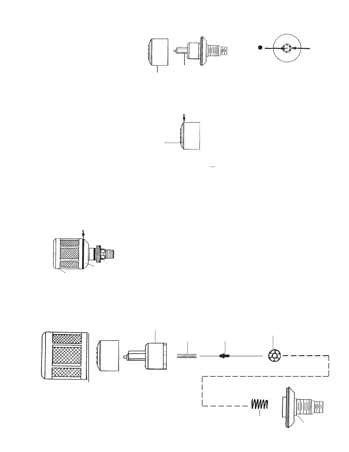
2. Using a knife edge, carefully pry apart
the float cover and bottom piece (See
Figure 5).
Float Guide
Be sure to reassemble all parts as shown
into the float guide. Snap float guide cover
into bottom piece.
Small
Spring
Float
Guide
Cover
Bottom
Piece
Large
Spring
Actuator
Pin
Flat view of
Spring Disc
HAF18 Automatic Drain
Float Guide
Float
Float
Stem
Rubber
Seal
Pry apart with knife edge.
7. Replace the float cap (again, be certain
the rubber seal, Figure 8, is in place).
8. Slide float over float guide.
9. Snap float cover onto bottom piece.
10. Install automatic drain into bowl. Be
sure o-ring is in place (between the
drain and bowl). Tighten the plastic
retaining nut firmly by hand.
11. Monitor the automatic drain for proper
operation. If it fails to operate properly,
replace with a new unit.
NOTE
If the Float Guide inadvertently
came apart, refer to Figure 9 and
instructions.
Cap
(Inside view of float)
Figure 7
Figure 6
Figure 9
Figure 8