Do you have a question about the DeVilbiss FA153-2 and is the answer not in the manual?
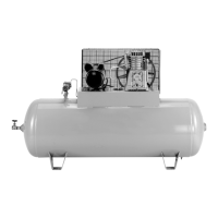
This document is an owner's manual for a permanently lubricated air compressor, designed for home use. It covers models FA153-2, FA153-3, FAC153-2, and FAC153-3.
The air compressor is designed to compress air for various applications, primarily for home use. It features a piston-driven pump that draws in air through intake valves, compresses it, and then forces it out through exhaust valves, a check valve, and into an air tank. The compressed air is stored in the tank until needed. A pressure switch automatically controls the motor, starting it when the tank pressure drops below a factory-set "cut-in" pressure (100 PSI) and stopping it when the tank pressure reaches a factory-set "cut-out" pressure (125 PSI). A regulator controls the air pressure available at the outlet, allowing users to adjust it to the specific requirements of their air tools or accessories. The unit also includes an outlet pressure gauge to indicate the regulated air pressure and a tank pressure gauge to show the reserve air pressure. A unique air intake system means no traditional air filter is required. The compressor incorporates an advanced cooling system with an engineered fan to prevent overheating. A drain valve at the base of the air tank allows for the removal of condensation after use.
The manual provides a detailed specification chart for the listed models:
The compressor is designed for straightforward operation. Before use, the "ON/OFF" switch should be set to "OFF," and the air regulator or shut-off valve closed. After attaching the air hose and accessories, the switch is moved to "ON/AUTO" to allow the tank pressure to build. Once the motor stops at the "cut-out" pressure, the regulator can be opened and adjusted clockwise to the desired pressure setting. The compressor is then ready for use. It is crucial to operate the compressor in a well-ventilated area, free of flammable vapors, and not near the spray area if using it for painting. The manual emphasizes checking the maximum pressure rating of air tools and accessories to prevent bursting hazards, ensuring the regulator outlet pressure never exceeds these ratings.
For proper electrical connection, the compressor requires a 3-wire extension cord with a 3-blade grounding plug and a 3-slot receptacle. If an extension cord is necessary, it should be in good condition, no longer than 50 feet, and 14 gauge (AWG) or larger (12AWG, 10AWG, or 8AWG are also acceptable; 16 or 18 AWG should not be used).
A "break-in" procedure is required before the first use and when the check valve is replaced. This involves setting the pressure switch to "OFF," plugging in the power cord, opening the regulator fully to prevent pressure build-up, moving the switch to "ON/AUTO," running the compressor for 15 minutes with the regulator open, and then closing the regulator to allow the tank to fill to cut-out pressure.
Regular maintenance is essential for the longevity and safe operation of the compressor. The manual highlights the importance of draining condensed water from the air tank daily or after each use to prevent rust and thinning of the steel tank, which could lead to a violent tank explosion. If the tank develops a leak, it must be replaced immediately. The compressor should be stored in a clean, dry location, and the electrical cord and air hose should be protected from damage by winding them loosely around the unit.
The troubleshooting guide provides solutions for common issues, such as excessive tank pressure (safety valve pops off), air leaks at fittings, check valve, or pressure switch release valve, and the motor not running. It also addresses issues like knocking noise and insufficient air supply. For repairs, especially electrical wiring or component replacement, it is strongly advised to consult an authorized service center. The manual explicitly warns against drilling into, welding, or modifying the air tank, as this can weaken it and cause it to rupture or explode. It also cautions against unauthorized modifications to pressure-controlling components like the unloader valve or safety valve.
The compressor is designed for a 50% duty cycle, meaning it should not pump air for more than 30 minutes in any given hour to prevent misuse and ensure it is not undersized for the required air demand. The cooling system is designed to maintain proper operating temperature, and users are advised to keep ventilation openings clear of obstructions.
| Brand | DeVilbiss |
|---|---|
| Model | FA153-2 |
| Category | Air Compressor |
| Language | English |