© 2013 Finishing Brands UK Ltd. 13
Parts Replacement/Maintenance
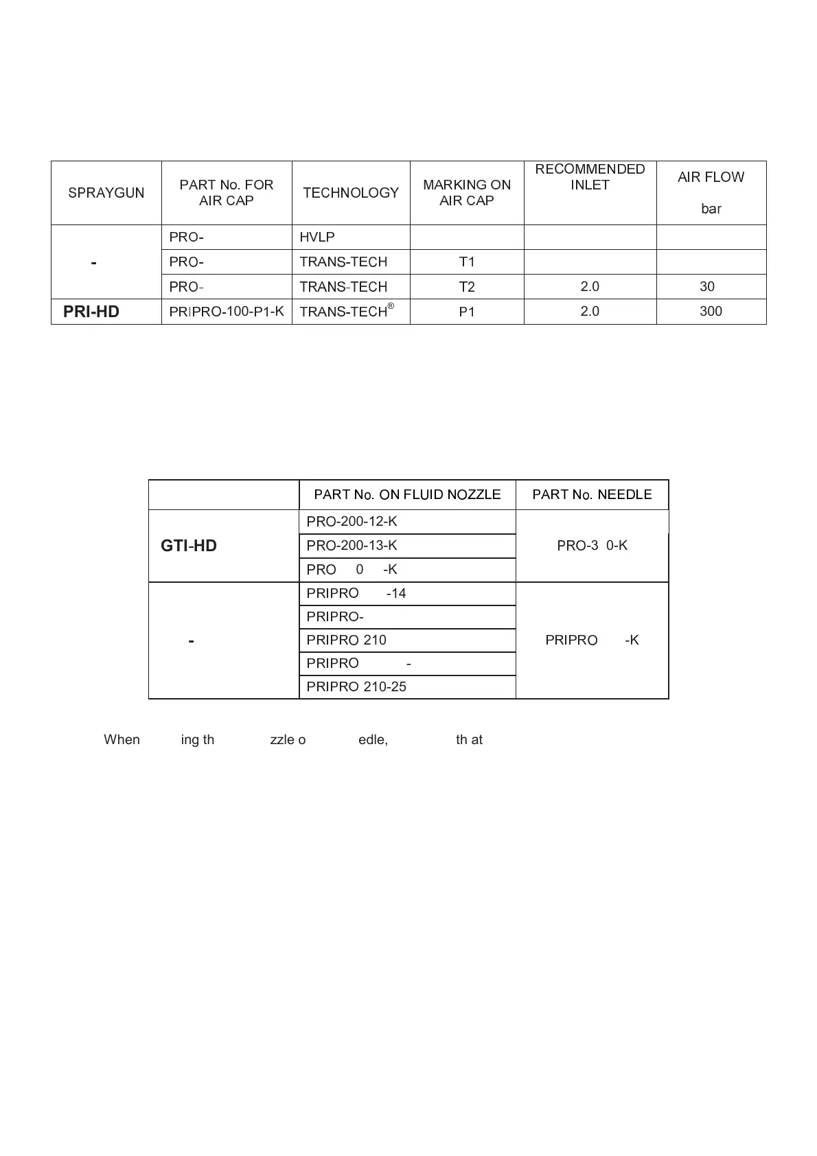
Chart 1 – Air Caps
NOTE: When removing air cap from retaining ring, don’t remove the Slip Ring (2) or Retaining Ring Seal (5) from
the Retaining Ring. Damage to the parts may occur. Slip ring and Retaining Ring seal are not available as
replacements. Simply wipe parts clean and reassemble with new or clean air cap.
Chart 2 – Fluid Nozzle Range & Fluid Needle
SPRAYGUN
NOTE: When replacing the fluid nozzle or fluid needle, replace both at the same time. Torque to 18–20 nm (13–15
ft-lbs). Don’t over tighten the fluid nozzle. Use SN-28 10mm Spanner supplied with the gun and check with a torque
wrench.
IMPORTANT NOTE: The GTI-HD and PRI-HD tips and aircaps ARE NOT INTERCHANGEABLE
between the 2 models. Any attempt to fit tips or caps onto the wrong Spray Gun may cause
damage to the parts or the Spraygun body and invalidate the warranty.