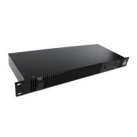
Device overview
1. Volume controls
2. Signal LED indicator
3. Limiter LED indicator
4. Power LED indicator
5. ON/OFF switch
6. Rack mount brackets
7. Ventilation slots
8. Ground lift switch
9. Mode switch
10. Signal input section (Balanced XLR / 6.35 mm TRS jack)
11. Cooling fans
12. Speaker output section (Speaker-lock)
13. Power input connector + fuse holder
14. AC voltage switch 100 / 240V
Any information and illustrations shown in this user manual are subject to change without further notice.
User manual version: 4.0 Creation date + author initials: 11-12-2015 RV Revision date + author initials: 10-12-2015 RV
1
1
2
2
3
4
6
5
7
8
9
10
11
12
13
3
6
11
14