ENGLISH
6
supervised by a person responsible for their
safety. Children should never be left alone with
this product.
Electrical Safety
The electric motor has been designed for one
voltage only. Always check that the power supply
corresponds to the voltage on the rating plate.
Your DEWALT tool is double insulated in
accordance with EN 60745; therefore no
earth wire is required.
WARNING: 120 V units have to
be operated via a fail-safe isolating
transformer with an earth screen
between the primary and secondary
winding.
If the supply cord is damaged, it must be replaced
by a specially prepared cord available through the
D
EWALT service organisation.
Mains Plug Replacement
(Middle East and Africa)
If a new mains plug needs to be fitted:
• Safely dispose of the old plug.
• Connect the brown lead to the live terminal in
the plug.
• Connect the blue lead to the neutral terminal.
WARNING: No connection is to be
made to the earth terminal.
Follow the fitting instructions supplied with good
quality plugs. Recommended fuse: 13 A.
Using an Extension Cable
If an extension cable is required, use an approved
extension cable suitable for the power input of this
tool (see Technical Data). The minimum conductor
size is 1 mm
2
; the maximum length is 30 m.
When using a cable reel, always unwind the cable
completely.
ASSEMBLY AND ADJUSTMENTS
WARNING: To reduce the risk of
injury, turn unit off and disconnect
machine from power source before
installing and removing accessories,
before adjusting or changing set-
ups or when making repairs. Be sure
the trigger switch is in the OFF position.
An accidental start-up can cause injury.
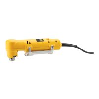
Selecting the Operating Mode (fi g. 4)
The tool can be used in two operating modes:
Rotary drilling: for steel, wood and
plastics.
Percussion drilling: simultaneous rotating
and impacting for concrete and masonry
drilling operations.
Select the required operating mode by rotating the
mode selector (e) to the required position.
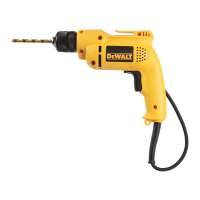
Inserting and Removing a Bit (fi g. 1)
1. Open the chuck by turning the sleeve (i)
counterclockwise and insert the bit shank.
2. Put the chuck key (j) into each hole in the side
of the chuck and turn clockwise until tight.
3. To remove the bit, proceed in reverse order.
Fitting the Side Handle (fi g. 1)
The side handle (f) can be fitted to suit both RH- and
LH-users.
WARNING: Always use the drill with the
side handle properly assembled.
1. Loosen the side handle.
2. For RH-users, slide the side handle clamp over
the collar behind the chuck, handle at the left.
3. For LH-users, slide the side handle clamp over
the colar behind the chuck, handle at the right.
4. Rotate the side handle to the desired position
and tighten the handle.
Setting the Drilling Depth (fi g. 3)
1. Insert the required drill bit into the chuck.
2. Slacken the side handle (f).
3. Fit the depth adjustment rod (g) through the
hole in the side handle clamp.
4. Adjust the drilling depth as shown.
5. Tighten the side handle.
Forward/reverse Slider (fi g. 1)
To select forward or reverse rotation, use the
forward/reverse-switch (c) (see arrow on tool).
WARNING: Always wait until the motor
has come to a complete standstill
before changing the direction of rotation.