English
6
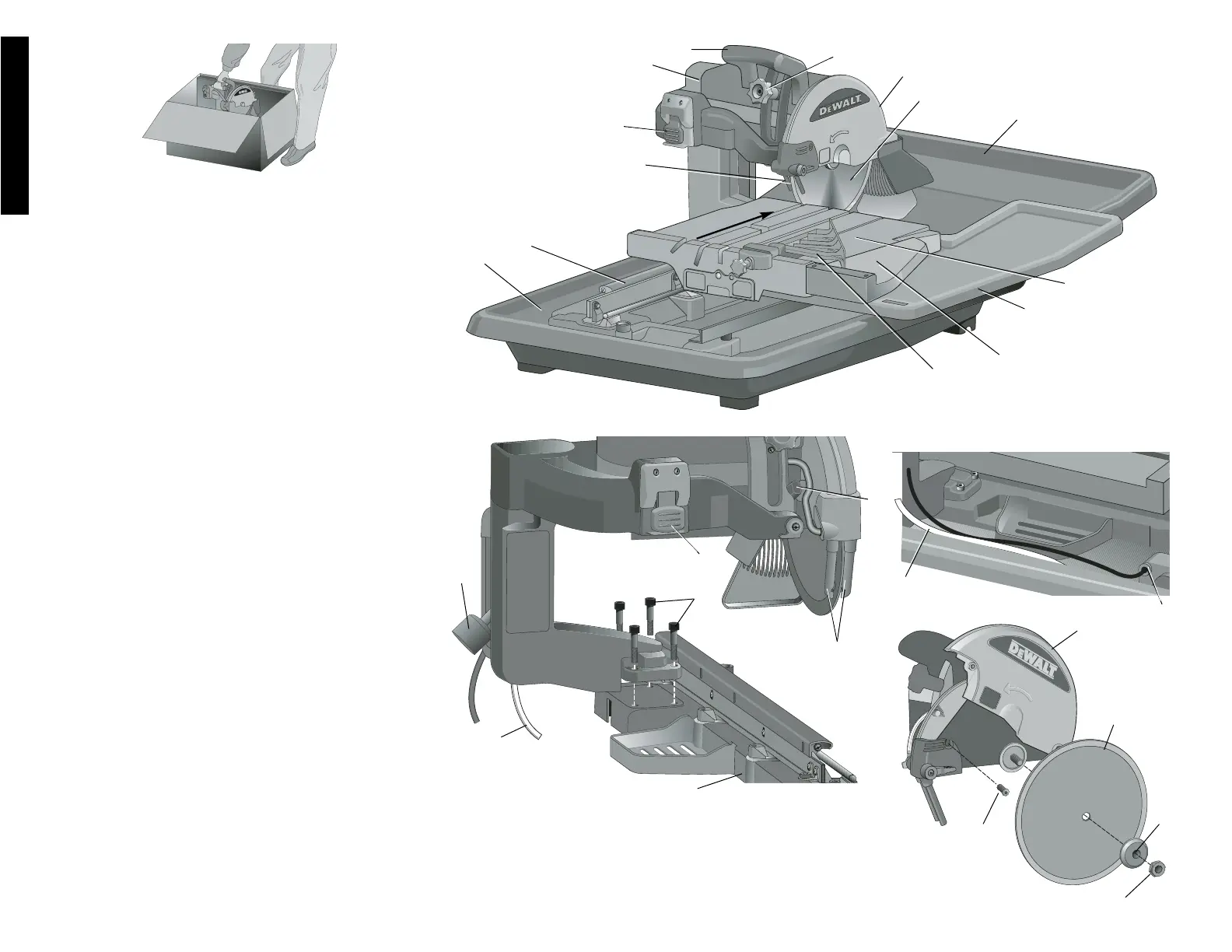
FEATURES (Fig. 2–4)
The motor arm assembly comes assembled. Open the
box and lift the assembly out, as shown in Figure 1.
A On/Off switch I. Cutting cart water
B. Motor arm assembly attachment
C. Plunge handle J. Edge guide
D. Head lock knob K. Water pan
E. Cutting wheel cover L. Saw frame assembly
F. Cutting wheel M. Water nozzles
G. Rear water attachment N. Water pump
H. Cutting cart assembly PP. Cutting Cart Extension
ASSEMBLY (Fig. 2–4)
1. Place saw frame assembly (L) on a stable surface.
2. Using the supplied wrench remove the screws (O)
from the saw frame assembly.
3. Place motor arm (B) on frame assembly.
4. Secure the saw head by installing two of the screws
(O) into the holes closest to the rail. Tighten the screws
with the wrench provided. Install the other two screws
in the other two holes and tighten.
5. Place the saw assembly into the water pan (K) as
shown in Figure 2.
6. Tilt the front of the cutting cart assembly (H) down on
a slight angle. Align the arrow on the rear of the cutting
cart with the round rail on the frame of the saw. Slide
the cutting cart assembly onto the rail system clearing
the cart stop with both pairs of rollers.
7. Place the threaded fitting onto the water pump (N).
Attach the clear water tube (P) to the threaded fitting
(Fig. 4). Place the water pump in the deep corner of
the water pan, near the drain plug. Insert the pump
power cord into the socket (Q).
8. Install rear water attachment (G).
9. Install cutting cart water attachment (I).
TO ATTACH CUTTING WHEEL (FIG. 5)
1. Using the smaller Allen wrench supplied, loosen (do
not remove) the screw (R) on the side of the cutting
wheel cover (E). Pull the rubber side flap back and lift
the cover toward the rear of the saw.
2. Press spindle lock button. Remove the cutting wheel
nut (S) with hex wrench provided. Remove outer
flange (T).
3. Install the cutting wheel (F) with the rotational arrow
facing the same way as on the rotational arrow on the
FIG. 1
A
K
H
G
F
FIG. 2
B
FIG. 3
O
L
P
FIG. 5
S
E
R
F
N
L
P
Q
O
A
E
U
FIG. 4
J
M
M
C
D
I
T
CUTTING DIRECTION
PP