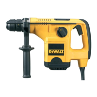
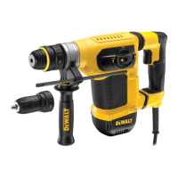
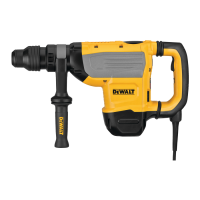
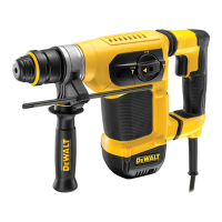
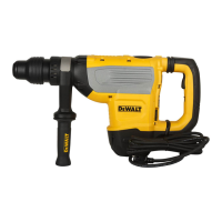
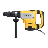
This document describes the DEWALT Heavy-Duty Rotary Hammerdrill models D25112(C), D25113, D25114, and D25213. These tools are designed for professional drilling, hammerdrilling, screwdriving, and light chipping applications. They are not intended for use in wet conditions or in the presence of flammable liquids or gases. These are professional power tools, and children should not have contact with them. Supervision is required when inexperienced operators use these tools.
The rotary hammerdrills are equipped with a torque limiting clutch. This feature reduces the maximum torque reaction transmitted to the operator if a drill bit jams, and it also prevents the gearing and electric motor from stalling. The torque limiting clutch is factory-set and cannot be adjusted.
Function Description
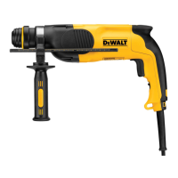
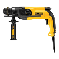
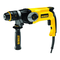
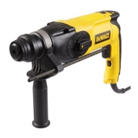
The tool features a variable speed switch (a) which controls the tool speed based on the pressure exerted. For continuous operation, a lock-on button (b) is available. A forward/reverse slider (c) allows for changing the direction of rotation. The mode selector switch (d) enables selection between different operating modes: rotary drilling, hammerdrilling, and hammering only (chiselling). A safety lock (e) is present to secure the mode selector. The tool holder (f) is designed for SDS Plus® bits, and a dust cover (g) helps prevent dust ingress into the mechanism. Some models (D25114) feature a locking collar (h) for replacing the tool holder with a chuck. A depth adjustment rod (i) and a depth stop clamp (k) are used for setting the drilling depth. A side handle (j) is provided for proper hand positioning and control.
Usage Features
- Selecting the Operating Mode:
- For rotary drilling (D25112(C)/D25113/D25114/D25213), set the mode selector switch (d) to the rotary drilling position. This mode is used for drilling in steel, wood, and plastics, and for screwdriving.
- For hammerdrilling (D25112(C)/D25113/D25114/D25213), set the mode selector switch (d) to the hammerdrilling position. This mode is used for hammerdrilling in concrete and masonry.
- For hammering only (chiselling) (D25113/D25114/D25213), set the mode selector switch (d) to the "hammering only" position. This mode is used for light chipping and chiselling applications.
- For rotary drilling without hammer action (D25112(C)/D25113/D25114/D25213), set the mode selector switch (d) to the rotary drilling position. This mode is used for drilling in steel, wood, and plastics, and for screwdriving.
- For bit rotation without hammer action (D25213), set the mode selector switch (d) to the bit rotation position. This mode is used for non-rotation chisel use.
- Always ensure the mode selector switch is securely locked in place.
- Inserting and Removing SDS Plus® Accessories:
- Clean and grease the bit shank.
- Insert the bit shank into the tool holder (f).
- Push the bit down and turn it slightly until it fits into the slots.
- Pull on the bit to check if it is properly locked. The SDS Plus® system allows the bit to move axially several centimetres when locked in the tool holder.
- To remove a bit, pull back the tool holder locking sleeve (l) and pull out the bit.
- WARNING: Always wear gloves when changing accessories. The exposed metal parts on the tool and accessory may get extremely hot during operation.
- Fitting the Side Handle:
- The side handle (j) can be fitted to suit both right- and left-hand users.
- WARNING: Do not use the tool without the side handle properly assembled.
- For right-hand users, slide the side handle clamp over the collar behind the tool holder, handle at the right.
- For left-hand users, slide the side handle clamp over the collar behind the tool holder, handle at the left.
- Rotate the side handle to the desired position and tighten the handle.
- Setting the Drilling Depth:
- Insert the required drill bit.
- Press the depth stop clamp (k) and keep it depressed.
- Fit the depth adjustment rod (i) through the hole in the depth stop clamp.
- Adjust the drilling depth as shown.
- Release the depth stop clamp.
- Forward/Reverse Slider:
- For D25112(C)/D25113/D25114, push the forward/reverse slider (c) to the RH-side for forward (RH) rotation or to the LH-side for reverse (LH) rotation.
- For D25213, push the forward/reverse slider (c) to the LH-side for forward (RH) rotation or to the RH-side for reverse (LH) rotation.
- WARNING: Always wait until the motor has come to a complete standstill before changing the direction of rotation.
- Fitting the Chuck Adapter and Chuck (D25112(C)/D25113/D25213):
- Screw the chuck onto the threaded end of the chuck adapter.
- Insert the connected chuck and adapter in the tool as though it were a standard SDS Plus® bit.
- To remove the chuck, proceed as for removing a standard SDS Plus® bit.
- WARNING: Never use standard chucks in the hammerdrilling mode.
- Replacing the Tool Holder with the Chuck (D25114K):
- Turn the locking collar (h) into the unlocking position and pull the tool holder (f) off.
- Push the chuck (m) onto the spindle and turn the locking collar into the locking position.
- To replace the chuck with the tool holder, first remove the chuck the same way as the tool holder was removed. Then place the tool holder the same way as the chuck was placed.
- Replacing the Dust Cover:
- Pull back the tool holder locking sleeve (l) and pull the dust cover (g) off.
- Fit the new dust cover.
- Release the tool holder locking sleeve.
- Instructions for Use:
- Always observe safety instructions and applicable regulations.
- Be aware of the location of pipework and wiring.
- Apply only gentle pressure to the tool (approx. 5 kg). Excessive force does not speed up drilling but decreases tool performance and may shorten tool life.
- Do not drill or drive too deep to prevent damage to the dust cover.
- Always hold the tool firmly with both hands and ensure a secure stance. Always operate the tool with the side handle properly mounted.
- Proper Hand Position:
- Requires one hand on the side handle (j), with the other hand on the main handle (o).
- WARNING: To reduce the risk of serious personal injury, ALWAYS use proper hand position as shown.
- WARNING: To reduce the risk of serious personal injury, ALWAYS hold securely in anticipation of a sudden reaction.
- Switching On and Off (D25112(C)/D25113/D25114):
- To run the tool, press the variable speed switch (a). The pressure exerted on the variable speed switch determines the tool speed.
- For continuous operation, press and hold down the variable speed switch, press the lock-on button (b) and release the switch.
- To stop the tool, release the switch.
- To stop the tool in continuous operation, press the switch briefly and release it.
- Always switch off the tool when work is finished and before unplugging.
- Switching On and Off (D25213):
- To run the tool, press the variable speed switch (a). The pressure exerted on the variable speed switch determines the tool speed.
- To stop the tool, release the switch.
- To lock the tool in off position, move the forward/reverse slider (c) to the central position.
- Hammerdrilling with a Solid Bit:
- Set the mode selector switch (d) to the hammerdrilling position.
- Insert the appropriate drill bit (high quality carbide-tipped bits recommended).
- Adjust the side handle (j) as required.
- If necessary, set the drilling depth.
- Mark the spot where the hole is to be drilled.
- Place the drill bit on the spot and switch on the tool.
- Always switch off the tool when work is finished and before unplugging.
- Hammerdrilling with a Core Bit:
- Set the mode selector (d) to the hammerdrilling position.
- Adjust the side handle (j) as required.
- Insert the appropriate core bit.
- Assemble the centerdrill into the core bit.
- Place the centerdrill on the spot and press the variable speed switch (a). Drill until the core penetrates into the concrete approx. 1 cm.
- Stop drilling and remove the centerdrill. Place the core bit back into the hole and continue drilling.
- When drilling through a structure thicker than the depth of the core bit, break away the round cylinder of concrete or core inside the bit at regular intervals. To avoid unwanted breaking away of concrete around the hole, first drill a hole the diameter of the center drill completely through the structure. Then drill the cored hole halfway from each side.
- Always switch off the tool when work is finished and before unplugging.
- Rotary Drilling:
- Set the mode selector switch (d) to the "rotary drilling" position.
- For D25112(C)/D25113/D25213, fit the chuck adapter/chuck assembly.
- For D25114, replace the tool holder with the chuck.
- Proceed as described for hammerdrilling.
- WARNING: Never use standard chucks in the hammerdrilling mode.
- Screwdriving:
- Set the mode selector switch (d) to the rotary drilling position.
- Select the direction of rotation.
- For D25112(C)/D25113/D25213, insert the special SDS Plus® screwdriving adaptor for use with hexagonal screwdriver bits.
- For D25114K, replace the tool holder with the chuck.
- Insert the appropriate screwdriver bit. When driving slotted head screws always use bits with a finder sleeve.
- Gently press the variable speed switch (a) to prevent damage to the screw head. In reverse (LH) rotation the tool speed is automatically reduced for easy screw removal.
- When the screw is flush with the workpiece, release the variable speed switch to prevent the screw head from penetrating into the workpiece.
- Chipping and Chiselling (D25113/D25114/D25213):
- Set the mode selector switch (d) to the "hammering only" position.
- Insert the appropriate chisel and rotate it by hand to lock it into one of 51 positions.
- Adjust the side handle (j) as required.
- Switch on the tool and start working.
Maintenance Features
The DEWALT power tool is designed for long-term operation with minimal maintenance. Proper tool care and regular cleaning are essential for satisfactory operation.
- WARNING: To reduce the risk of injury, turn the unit off and disconnect the machine from the power source before installing or removing accessories, adjusting or changing set-ups, or making repairs. Ensure the trigger switch is in the OFF position to prevent accidental start-up.
- This machine is not user-serviceable. After approximately 40 hours of use, or if problems occur earlier, the tool should be taken to an authorised DEWALT repair agent.
- The tool will automatically switch off when the carbon brushes are worn.
- Motor Brushes: DEWALT uses an advanced brush system that automatically stops the drill when the brushes wear out, preventing serious damage to the motor. New brush assemblies are available at authorised DEWALT service centers. Always use identical replacement parts.
- Lubrication: The power tool requires no additional lubrication. Accessories and attachments used must be regularly lubricated around the SDS Plus® fitment.
- Cleaning:
- WARNING: Blow dirt and dust out of the main housing with dry air as often as dirt is seen collecting in and around the air vents. Wear approved eye protection and an approved dust mask when performing this procedure.
- WARNING: Never use solvents or other harsh chemicals for cleaning the non-metallic parts of the tool. These chemicals may weaken the materials used in these parts. Use a cloth dampened only with water and mild soap. Never let any liquid get inside the tool; never immerse any part of the tool into a liquid.