FIG, 1 FIG, 2 H FIG 4
B
\
c
I J
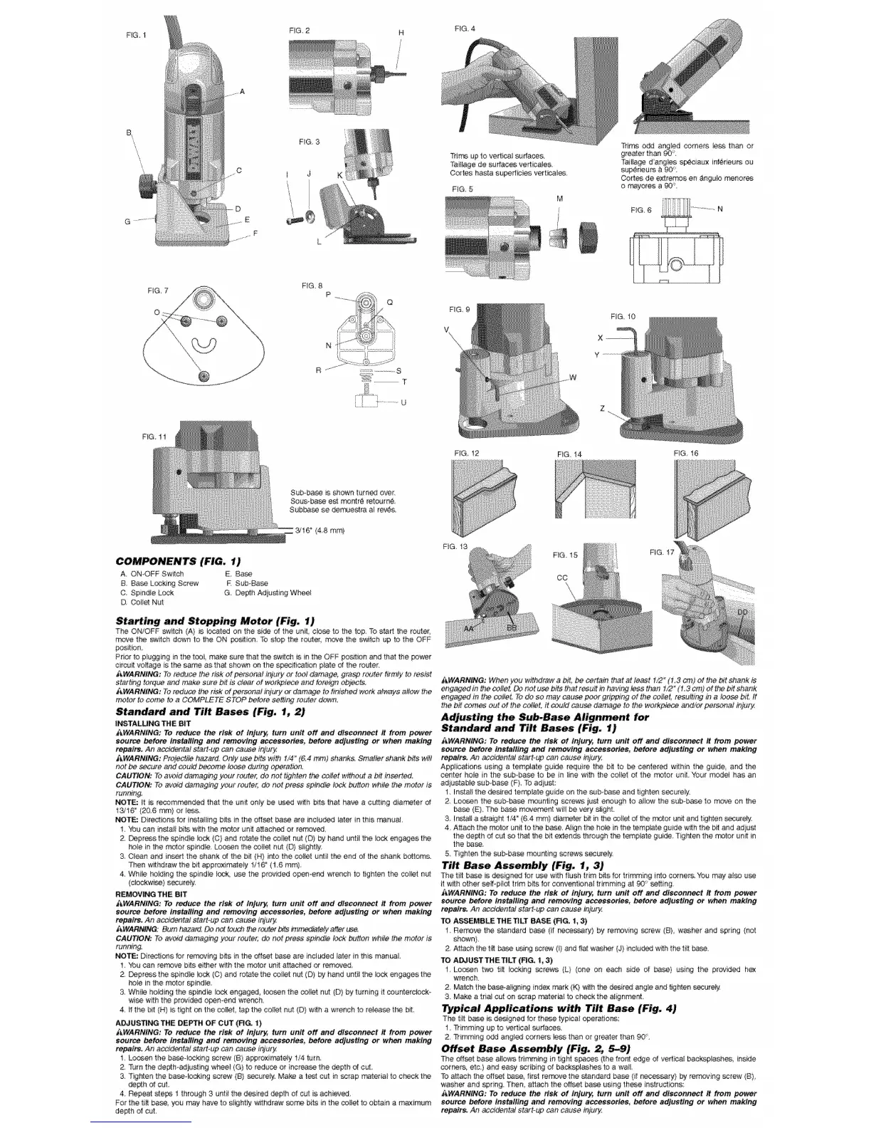
Trim up to vert_co_surface&
Tml_agede sudaces verticole&
Cortes haste supedic_es verticoles
FIG, 5
Trims odd angled corners leve than or
greater then 90'.
Taillage dangles speciau× nf_r_urs ou
sa_rieurs _ 90'
Cortes de extremco en angu_omenor_
o r_yeres a _°.
FIG 8
N 1} .....
........ ....,>)
a ?:?: i ................
FIG 10
FIG, 12 F_G, 14 FIG 16
Sub-ba_ rss!_n turned over.
Seve Lase est men:re re:same
Sub_ se demuestra a! rests.
{4,8 mm)
COMPONENTS (FIG. 1)
A, ONOFF Sw_tch E Base
B. Ba_ LoskJnf_Screw R Sub-Base
C, Spindle Leak G. Depth Adjuring Whee_
D, Colfet Nut
Starting and Stopping Motor (Fig, 1)
The ON7OFF _wilch {A) _sbcoted on the side of the un_, ci_ve to the top. Tostart the router_
move the swr_ch down to the ON _sition, To stop the raster, rseve the s_atch up to the OFF
posit©n,
Prior to ptugging in the too_ make sure that the switch is in tee OFF posit©n and that the powe_
circuit voyage is t_ same as th_ shown on the specif_ca_on plate of the router.
J_WARNING; To re_ce the fisRet perser_ injury or ted _mage, 9fa_ rc_der hrmJy to resist
atatt#_g tarq_ &nd make sure bit _sdea_*et wovkpiece and tore_gnobjects.
_WARNING: To reduce the risk of personal ihiuP/ or dar_ge to f_vshed work a_'w_ysallow the
motor to come to a COMPLETE STOP he.re se_ router down,
Stan_ and Tilt Bases (Fig. 1, 2)
INSTALLING THE BIT
Z_WARNING: To reduce the risk of Injury_ turn Unit Off and disconnect # from power
sour_ before installing and removing accessories, before adjusting or when making
repairs. An aas_dentat start..up can _use ie/u_y.
AWARNING: Prelec_jle h_anJ, Only use bits wi_ 1/4_(BA nr}m)shank& Smd_r shank bits wilt
not _ secure and ceutd b_ome levee du_ing epees:ion.
CAUTION: To avoid damaging }_ourreute_: de eat tighten the co#at without a bit inserted.
CAUTION: To avoid damagieg y_f r_tet, do not prove sp_ndtef_k bu#on wh#e the nora{ ts
funnlng_
NOTE; it is recommended that the un_ only be used w_h bits that haue a cutting diameter of
t3/lB _(206 ram) of fee&
NOTE: D}rectk*ns for ivetalling bits in the of:set ba_ are instu_d later in this rranual,
1.You ca_ in,all bi_ with the motor un_ attached or remov_
2.,Depr_S the sptndle ©ck (O) and rotate the cone: as: (D} by hand until _e Io_ engages the
ho_ein the mcto_ splndte. Learn tee ca_iet nut (D) slight{y:
3 Ci_n arid veer: the shank of the bit (H) into the co_et unti_ the end of the _'_ank be:toms.
Then w_hdraw the bit apprexima_eiy 1/16_ (16 ram)
4 While hoidmg the sp_nd_elock, use the provided open-end wrench to tighten the col/e: nut
(cbckwlse) s_urely.
REMOVING THE BIT
_&WARNL_tG: To reduce the risk' of lr_ur_ turn unit off and disconnect it from power
source before installing and t_'noving accessories, before adjusting or when making
repairs. An aaside_taJ start-gp can _3use iGlu<y
/__WARNI._: Bum h_#_d. Do t_ teu_ ff_'aroute_b#s #nm_iate#/ at:el yea.
CAUTION: Toavdd damaging your r_teL _ not prove spindle _ck button white the motor is
Fdat}a?g_
_TE: Directions for rer-novtrg bits in the off_! _ a_e included tater in this manual
! You ca_ re_'r_ve bits e{ther w_ththe _tor ue_ attached or removed
g. Depress the spmdle _ask(C) and rotate the cooer nut (D} by hand until the #ck engages the
holeinthem_o{ spindle,
3 While he#rag the spnd_ iO_ engaged I_sen the col_et nut (O) bytummg It counterciock
wi_ w_h the provided o_mend wrench,
4. If the bit (H) _stight er_the _llet tap the sotIet nut (D) w_h a wrench to re_ t_ #_t.
ADJUSTING THE DEPTH OF CUT (FIG, 1)
_&WARNING: To reduce the risk of tnJurJ4turn unit off and disconnect# from power
scuttle before instal/#_g and removing accessories, before adjusting or when making
rei_lr_ An aveidef_tal start-up can cause injury
1 Leveen the base4ockmg sorew (B) a_roxirvetety !/_ turn.
& Turn the de_h adjusting whee{ (G) te redu_ or increa_ the depth of cut
3 Tighte_ the baseoiockmg screw (B) _urety, Ma_ a te_ cut in scrap material to check the
_h of cut.
4 Repeat _e_ t through 3 until the d_ired depth d cut is achieved
FO_'the tilt ba_, you may have to st_htIy withdraw _ bts i_ the ceiiet to obtain a maximum
depth of cut.
FiG. 15
CO
/_WARNING: When yea withdraw a bit, be _erta#_ that at feast 1/2"(t,3 cm) at the t_t shank is
engaged in _e asfle_ _ not use bits that resuR in havir_ _easthan f,_ (I.3 crn) et tk_ bit s_ank
engaged it} the co%at.To do so may _ase peo_ g#p_ng ot the cel_e_ _esuiting in a loose bit. it
the bit _re_ eu_d the sollet, it asukJ cease dan}age te the workplace &,}d/_ personal injur_
Adjusting the Sub-Base Alignment for
Standa_ and Tilt Bases (Fig. 1)
_WARNiNG: To reduce the risk of injury, turn unit off and disconnect it from power
source before installing and removing acceseories, before adjusting or when making
repairs. Ae accidental star,up can cause injut_
AppI_catass using a template guide require the b_ to be cente_'ed within the guide and the
center hole in the suboba_ !o be in _inewith tl_e co_et of the motor un_. Your _del has an
adducable eub-ba_ (F} To adjast:
1 I_alf the desir_ template guide o_ the sub-_ and tighten secUre_
2 Lo_n the suboba_ moaning screws just enough to allow the sub-base to m©ve on the
ba_ (E) The base movement witl _ very sight
3 fns_a#a straig_ 1/4" _64 ram) d_ameterbit in tee _it_ d the rotatorun_ and tighien _ure_.
4. Attach the rnoto_ unit to the base, Aiign the hole in the :empire guide with the bit and adiust
the depth of cut so treatthe _t extends through t_ template guide Tighten the _ter unit in
the _.
5i Tighten the su_ba_ mount _g _fews ssoure#y
Tilt _se Assembly (Fig. 1, 3)
The ti_t base is designed for uae w_lhflush trim bits for trimming into comers, You may also u_
it w_h other self-pi/_ trim b_s for conventional trimming at _ asking,
_WARNING: To reduce the risk of injury, turn unit off and disconnect it ft_m power
eeurce before tnetalilng and removing a_essoriee, before adjusting or when making
repalre. An asddental starto_t_can cause L_'ury.
TO AS-SEMBLE THE TILT BASE (FIG. 1, 3)
I Remove tt_ s_andard base (it nece_ry} by rer_yvi_g _rew (B} washer and spring (not
shown}
2 At_ch the h_ _se using _rew (t) and fiat washer {J) {r_tuded with the ti_tbase
TO ADJUST THE TILT (FIG. I,3)
1 Leaven two ti_ k._ckJngscrews (L) (one on eash side of _se} us{_ the provk_ed h_
wrench.
2 Match the base-aligning index mark (K) w_h the d_red angle and tighten securety
g Make a triat cut on ssrap m,eternal to eheekthe aI_n_nt
fypical Applications with Tilt Base (Fig. 4)
The ti_ base _ designed for these _ypiea/operatior_s_
1, Trimming up to sertical _Jda_s+
2. Trimming odd angled c_ners _evethan or greater than 90 _,
Offset Base Assembly (Fig, 2, 5-9)
The oftvet ba_ allows trimming in tight s_ (the fror_ edge of verhca/backsp_shve, inside
comers, etc.) ar_ easy _ribir'_3 of backsplashes to a walt
Toattach the at:set base, first remove the standard base (if nec_ry) by removing sorew (B}
washer and spring. Then att_h the offset ba_ using these instructions:
AWARNING: To reduce the risk of injury, turn unit off and disconnect it from _wer
source befot'e installing and removing before adjusting or when making
repairs. An acddental start-_ can cause it}jUf_4

 Loading...