10
Assembly and adjustment
WARNING: Prior to assembly and
adjustment always unplug the tool.
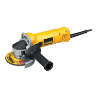
MOUNTING AND REMOVING THE GUARD (FIG. B1 & B2)
D28111/D28139 - GUARD WITH FIXING SCREW (FIG. B1)
• Place the angle grinder on a table, spindle up.
• Align the lugs (5) with the notches (6).
• Press the guard down and rotate it to the
required position.
• Securely tighten the screw (7).
• To remove the guard, slacken the screw.
WARNING: Never use the tool without
the guard in place.
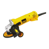
D28113(K)/D28130/D28132C/D28134/D28135(K)/D28141 -
KEYLESS GUARD (FIG. B2)
• Place the angle grinder on a table, spindle up.
• Release the clamping lock (8) and hold the guard
(3) over the tool as shown.
• Align the lugs (5) with the notches (6).
• Press the guard down and rotate it to the
required position.
• If required, increase the clamping force by
tightening the screw (9).
• Tighten the clamping lock.
• To remove the guard, release the clamping lock.
WARNING: Never use the tool without
the guard in place.
FITTING AND REMOVING A GRINDING OR CUTTING DISC
(FIG. C1 & C2)
• Place the tool on a table, guard up.
• Fit the inner fl ange (10) correctly onto the spindle
(11) (fi g. C1).
• Place the disc (12) on the fl ange (10). When
fi tting a disc with a raised center, make sure that
the raised centre (13) is facing the fl ange (10).
• Screw the outer fl ange (14) onto the spindle (11)
(fi g. C2):
– the ring on the fl ange (14) must face towards
the disc when fi tting a grinding disc (A);
– the ring on the fl ange (14) must face away from
the disc when fi tting a cutting disc (B).
• Press the spindle lock (2) and rotate the spindle
(11) until it locks in position.
• Tighten the fl ange (14) with the two-pin spanner
supplied.
• Release the spindle lock.
• To remove the disc, loosen the fl ange (14) with
the two-pin spanner.
WARNING: Do not use a damaged disc.
MOUNTING THE SIDE HANDLE (FIG. D)
• Screw the side handle (4) tightly into one of the
holes (14) on either side of the gear case.
Instructions for use
WARNING:
• Always observe the safety instructions
and applicable regulations.
• Ensure all materials to be ground or cut
are secured in place.
• Apply only a gentle pressure to the tool.
Do not exert side pressure on the disc.
• Avoid overloading. Should the tool
become hot, let it run a few minutes
under no load condition.
• Wear hearing protection and safety
glasses.
PRIOR TO OPERATION:
• Install the guard and appropriate disc or wheel.
Do not use excessively worn discs or wheels.
• Be sure the inner and outer fl ange are mounted
correctly.
• Make sure the disc or wheel rotates in the direction
of the arrows on the accessory and the tool.
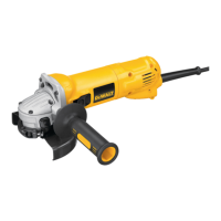
SWITCHING ON AND OFF (FIG. A)
• To run the tool, press the on/off switch (1).
• For continuous operation, press the switch
completely forward.
• To stop the tool, release the switch. To stop the
tool in continuous operation, press on the back
part of the switch.
WARNING: Do not switch the tool on or
off when under load.
ENGLISH
 Loading...