10
English
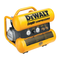
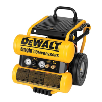
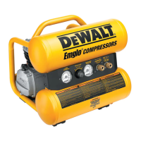
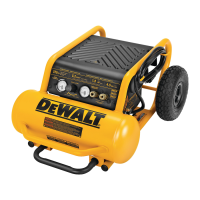
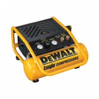
TANK PRESSURE GAUGE
The tank pressure gauge (B) indi-
D
C
E
B
cates the reserve air pressure in
the tank.
OUT
LET PRESSURE GAUGE
The outlet pressure gauge (C)
indicates the air pressure available
at the outlet side of the regulator.
This pressure is controlled by the regulator and is always less than
or equal to the tank pressure.
RE
GULATOR
The regulator (D) controls the air pressure shown on the outlet
pressure gauge. Turn regulator knob clockwise to increase pres-
sure and counterclockwise to decrease pressure.
UNIV
ERSAL QUICK CONNECT BODIES (IF EQUIPPED)
The universal quick connect body (E) accepts the three most
popular styles of quick connect plugs: Industrial, automotive, and
ARO. One hand push-to-connect operation makes connections
simple and easy. The two quick connect bodies allow the use of two
tools at the same time.
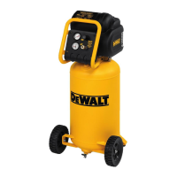
DRA
IN VALVE
The drain valve (H) is located at the base
H
of the air tank and is used to drain conden-
sation at the end of each use.
See Draining
Air Tank under Maintenance.
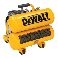
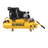
COOLING SYSTEM
This compressor contains an advanced design cooling system.
It is normal for this fan to blow air through the vent holes in large
amounts. The cooling system is working when air is expelled.
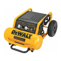
AIR
COMPRESSOR PUMP
The pump compresses air into the air tank. Working air is not
available until the compressor has raised the air tank pressure
above that required at the air outlet.
MO
TOR OVERLOAD PROTECTOR
This motor has a manual thermal overload
K
M
N
protector. If the motor overheats for any
reason, the overload protector will shut off
the motor. The motor must be allowed to
cool down before restarting. To restart:
1. Ensure the
On/Off switch (A) is in the
OFF position.
2. Allow the motor to cool.
3. Depress the reset button (M) on the
motor.
OIL
DIPSTICK
The oil dipstick (K) indicates the amount of oil in the pump. Check
pump oil daily, see Co
mpressor Pump Oil under Maintenance.
AIR INTAKE FILTER
The filter (N) is designed to clean air entering the pump. To ensure
the pump continually receives a clean, cool, and dry air supply the
filter must always be clean and the filter intake must be free from
obstructions.
INSTALLATION
Assembly
INSTALLING HOSES
WARNING: Risk of unsafe operation. Firmly grasp hose in hand
when installing or disconnecting to prevent hose whip.
1. E
nsure regulated pressure gauge reads 0 PSI (0 kPa).