MOTOR OVERLOAD PROTECTOR
The motor has a thermal overload protector. If the motor overheats for any reason, the
overload protector will shut off the motor. The motor must be allowed to cool down before
restarting. To restart:
1. Set the Mini-Switch to OFF(0) and unplug unit.
2. Allow the motor tocool.
3. Plug the power cord into the correct branch circuitreceptacle.
4. Set the Mini-Switch to ON(I) position.
INSTALLATION
Assembly
INSTALLING HOSES
WARNING: Risk of unsafe operation. Firmly grasp hose in hand when installing or discon-
necting to prevent hosewhip.
1. Ensure regulated pressure gauge reads 0 psi.
2. Grasp the hose at the quick connect plug and push the plug into the quick connect
body (E). Coupler will snap intoplace.
3. Grasp the hose and pull to ensure coupler isseated.
DISCONNECTING HOSES
WARNING: Risk of unsafe operation. Firmly grasp hose in hand when installing or discon-
necting to prevent hosewhip.
1. Ensure regulated pressure gauge reads 0psi.
2. Pull coupler on quick connect body back to release quick connect plug onhose.
FITTING THE WHEELS (FIG.4)
1. Insert the bolt through the wheel and bracket as shown in Fig.4.
2. Holding the locking nut in place with a wrench, tighten the wheel boltsecurely.
3. Repeat these steps for the oppositewheel.
FITTING THE BUMPERS (FIG.5)
1. Insert threaded bolt through the isolator and thread into the bracket hole as shown in
Fig.5. Tighten the boltsecurely.
2. Repeat these steps for the oppositebumper.
Grounding Instructions (Fig. 2)
WARNING: Risk of Electrical Shock. In the event of a short circuit, grounding reduces the
risk of shock by providing an escape wire for the electric current. This air compressor must
be properlygrounded.
The portable air compressor is equipped with a cord having a grounding wire with an appro-
priate grounding plug.
1. The cord set and plug (M) with this unit contains a grounding pin (L). This plug MUST be
usedwithagroundedoutlet(K).
IMPORTANT: The outlet being used must be installed and grounded in accordance with all
local codes and ordinances.
2. Ensure the outlet being used has the same configuration as the grounded plug. DO NOT
USE ANADAPTER.
3. Inspect the plug and cord before each use. Do not use if there are signs ofdamage.
4. If these grounding instructions are not completely understood, or if in doubt as to
whether the compressor is properly grounded, have the installation checked by a quali-
fiedelectrician.
DANGER: Risk of Electrical Shock. IMPROPER GROUNDING CAN RESULT IN
ELECTRICALSHOCK.
• Donotmodifytheplugprovided.Ifitdoesnotfittheavailableoutlet,acorrectoutlet
should be installed by a qualifiedelectrician.
• RepairstothecordsetorplugMUSTbemadebyaqualifiedelectrician.
Extension Cords
If an extension cord must be used, be sure it is:
• a3wireextensioncordthathasa3bladegroundingplug,anda3slotreceptaclethat
will accept the plug on the product
• ingoodcondition
• nolongerthan50feet(15.2m)
• 12gauge(AWG)orlarger.(Wiresizeincreasesasgaugenumberdecreases.10AWGand
8AWGmayalsobeused.DONOTUSE14OR16AWG.)
NOTICE: Risk of Property Damage. The use of an undersized extension cord will cause volt-
age to drop resulting in power loss to the motor and overheating. Instead of using an exten-
sion cord, increase the working reach of the air hose by attaching another length of hose to
its end. Attach additional lengths of hose asneeded.
Voltage and Circuit Protection
Refer to the Voltage and Minimum Branch Circuit Requirements under Specifications.
CAUTION: Risk of Overheating. Certain air compressors can be operated on a 15 amp
circuit if the following conditions are met.
• VoltagesupplytocircuitmustcomplywiththeNationalElectricalCode.
• Circuitisnotusedtosupplyanyotherelectricalneeds.
• Extensioncordscomplywithspecifications.
• Circuit is equipped with a 15 amp circuit breaker or 15 amp time delay fuse.
NOTE: If compressor is connected to a circuit protected by fuses, use only time delay
fuses. Time delay fuses should be marked “D” in Canada and “T” in the US.
If any of the above conditions cannot be met, or if operation of the compressor repeatedly
causes interruption of the power, it may be necessary to operate it from a 20 amp circuit. It
is not necessary to change the cordset.
Compatibility
NOTE: Always use an air line filter to remove moisture and oil vapor when sprayingpaint.
Location
Place the air compressor in a clean, dry and well ventilated area at least 12" (30.5 cm) away
fromthewallorotherobstructionsthatwillinterferewiththeflowofair.Keepthecompressor
away from areas that have dirt and/or volatile fumes in the atmosphere. These impurities may
clog the intake filter and valves, causing inefficient operation.
WARNING: The air compressor pump and shroud are designed to allow for proper cool-
ing. The ventilation openings on the compressor are necessary to maintain proper operating
temperature. Do not place rags or other containers on or near theseopenings.
Place the air compressor on a flat surface resting on the rubber feet andwheels.
ELECTRICAL
Refer to all safety instructions before using unit. Observe extension cord safety instructions
if necessary. Always place the switch to the OFF(0) position before removing the plug from
the outlet.
TRANSPORTING (FIG. 3)
Whentransportingthecompressorinavehicle,trailer,etc.,makesurethetankisdrainedand
the unit is secured with straps to prevent tipping. Use care when driving to prevent tipping
the unit over in the vehicle. Damage can occur to the compressor or surrounding items if the
compressor istipped.
LIFTING
Always use two people when lifting and lift from the recommended lift points (N). DO NOT
lift by wheels or shroud.
MOVING
CAUTION: The wheels and handle do not provide adequate clearance, stability, or
support for pulling the unit up and down stairs or steps. The unit must be lifted or
pushed up aramp.
1. Grasp handle of compressor and tilt compressor back to rest onwheels.
WARNING: Risk of Unsafe Operation. Ensure proper footing and use caution when rolling
compressor so that unit does not tip or cause loss ofbalance.
2.Whenlocationisreachedslowlylowercompressortoground.Always store compres-
sor in a vertical position resting on the rubber bumpers andwheels.
PREPARATION FOR USE
WARNING: Do not operate this unit until you read this instruction manual for safety,
operation and maintenanceinstructions.
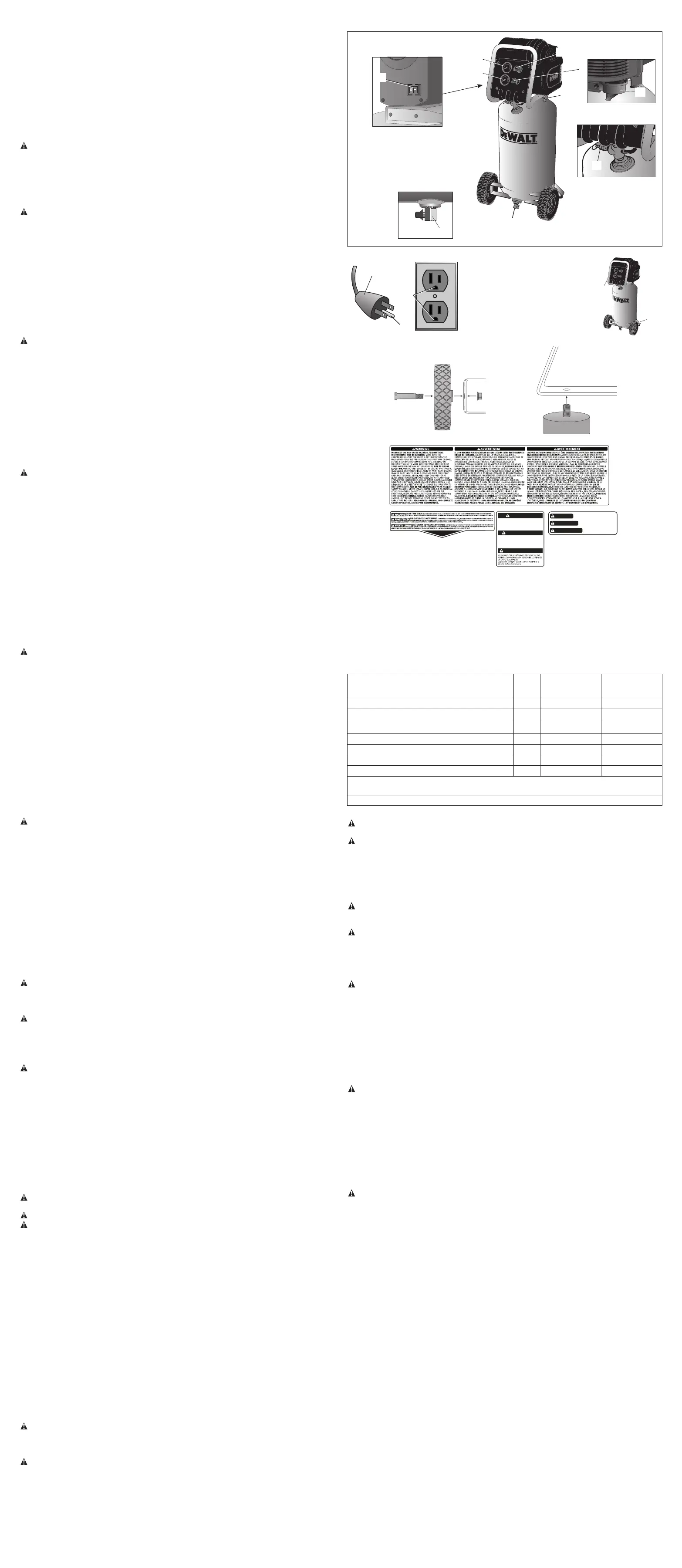
Pre-Start Checklist (Fig. 1)
1. Ensure the Mini-Switch (A) is in the OFF(0) position.
2. Plug the power cord into the correct branch circuit receptacle. See Voltage and Circuit
Protection underInstallation.
3. Ensure air tank is drained, see Draining Air Tank under Maintenance.
4. Ensure the drain valve (H) is closed.
5. Ensure safety valve (G) is functioning properly, see Checking Safety Valve
underMaintenance.
6. Pull the regulator knob (D) out and turn counterclockwise until fully closed. Ensure regu-
lated pressure gauge reads 0 psi. Push knob in to lock in place.
7. Attach hose and accessories. NOTE: Always use a minimum 3/8" (9.5 mm) or greater air
hose rated at 300 psi.
WARNING: Risk of unsafe operation. Firmly grasp air hose in hand when installing or dis-
connecting to prevent hosewhip.
WARNING: Risk of unsafe operation. Do not use damaged or wornaccessories.
WARNING: Risk of Bursting. Too much air pressure causes a hazardous risk of bursting.
Check the manufacturer’s maximum pressure rating for air tools and accessories. The regula-
tor outlet pressure must never exceed the maximum pressure rating.
OPERATING PROCEDURES
Start-up (Fig. 1)
1. Follow Pre-Start Checklist under Preparation forUse.
2. Move the Mini-switch to the ON(I) position and allow tank pressure to build. Motor will
stop when tank pressure reaches cut-outpressure.
NOTICE: Risk of Property Damage. Compressed air from the unit may contain wa ter conden-
sation and oil mist. Do not spray un fil tered air at an item that could be damaged by moisture.
Some air op er ated tools or de vic es may require filtered air. Read the in struc tions for the air
tool ordevice.
3.Adjustregulator(D)todesiredsetting.SeeRegulator underFeatures.
Shut-down (Fig. 1)
1. Move Mini-Switch (A) to the OFF(0) position.
NOTE: If finished using compressor, follow Steps 2–6.
NOTE: Whentheunithasbeenturnedoff,itisnormaltohearashorthissofairbeingreleased.
NOTE: Unplug unit when not inuse.
2. Pull the regulator knob (D) out and turn counterclockwise until fully closed. Ensure regu-
lated pressure gauge reads 0 psi. Push knob in to lock in place.
3. Remove hose andaccessory.
WARNING: Risk of unsafe operation. Firmly grasp air hose in hand when installing or dis-
connecting to prevent hosewhip.
4. Drain the air tank, see Draining Air Tank under Maintenance. Ensure air tank pressure
gauge reads 0psi.
WARNING: Risk of bursting. Drain air tank daily. Water will condense in air tank. If not
drained, water will corrode and weaken the air tank causing a risk of air tankrupture.
5. Allow the compressor to cooldown.
6.Wipeaircompressorcleanandstoreinasafe,nonfreezingarea.
MAINTENANCE
The following procedures must be followed when maintenance or service is performed on
the aircompressor.
1. Ensure Mini-Switch is in the OFF(0) position.
2. Remove air compressor plug fromoutlet.
3. Drain airtank.
4. Allow air compressor to cool down before startingservice.
NOTE: All compressed air systems contain maintenance parts (e.g., oil, filters, separators)
that are periodically replaced. These used parts may contain substances that are regulated
and must be disposed of in accordance with local, state, and federal laws andregulations.
NOTE: Take note of the positions and locations of parts during disassembly to make reas-
semblyeasier.
NOTE: Any service operations not included in this section should be performed by a DeWALT
factory service center or a DeWALT authorized servicecenter.
Maintenance Chart
Procedure Daily Weekly See tank
warning label
Check safety valve X
Inspect air filter X
Drain air tank X
Check for unusual noise/vibration X
Check for air leaks X
1
Clean compressor exterior X
Remove tank from service X
2
1Tocheckforairleaksapplyasolutionofsoapywateraroundjoints.Whilecompressor
is pumping to pressure and after pressure cuts out, look for air bubbles toform.
2 - For more information, call 1-833-913-1299
Checking Safety Valve
WARNING: Risk of bursting. If the safety valve does not work properly, over-pressurization
may occur, causing air tank rupture or anexplosion.
WARNING: Risk from flying objects. Always wear certified safety equipment: ANSI Z87.1
eye protection (CAN/CSA Z94.3) with side shields when using thecompressor.
Before starting compressor, pull the ring on the safety valve to make sure that the safety
valve operates freely. NOTE: Ring may be difficult to pull when air tank pressure is at 0 psi.
If the valve is stuck or does not operate smoothly, it must be replaced with the same type
of valve.
Draining Air Tank (Fig. 1)
WARNING: Risk of unsafe operation. Risk from noise. Air tanks contain high pres-
sure air. Keep face and other body parts away from outlet of drain. Use eye protection
[ANSI Z87.1 (CAN/CSA Z94.3)] when draining as debris can be kicked up into face.
WARNING: Risk from noise. Always wear proper hearing protection during use. Under
some conditions and duration of use, noise from this product may contribute to hearingloss.
NOTE: All compressed air systems generate condensate that accumulates in any drain point
(e.g. tanks, filter, aftercoolers, dryers). This condensate contains lubricating oil and/or sub-
stances which may be regulated and must be disposed of in accordance with local, state,
and federal laws andregulations.
WARNING: Risk of bursting. Drain air tank daily. Water will condense in air tank. If not
drained, water will corrode and weaken the air tank causing a risk of air tankrupture.
NOTICE: Risk of Property Damage. Drain water from air tank may contain oil and rust, which
can causestains.
1. Ensure Mini-Switch is in the OFF(0) position.
2. Place a suitable container under the drain valve (H) to catchdischarge.
3. Grasp lever on drainvalve.
4. Slowly rotate lever to gradually bleed air from airtank.
5.Whenairtankpressuregaugereads10psi,rotatevalvetothefullyopenposition.
6. Close drain valve whenfinished.
Checking Air Filter Element (Fig. 1)
WARNING: Hot surfaces. Risk of burn. Outlet tube, pump head, and surrounding parts are
very hot, do not touch. Allow compressor to cool prior to servicing.
1. Ensure Mini-Switch is in the OFF(0) position.
2. Allow unit tocool.
3. Remove filter cover (J) from base.
4. Remove element from filter base.
5. Place new element back in filter base. Purchase replacement parts from your local dealer
or authorized service center. Always use identical replacement parts.
6. Snap filter cover to filter base.
NOTICE: Risk of unsafe operation. Do not operate without air inlet filter
Accessories
WARNING: The use of any other accessory not recommended for use with this tool
could be hazardous. Use only accessories rated equal to or higher than the rating of the
aircompressor.
Recommended accessories for use with your tool are available for purchase from your local
dealer or authorized service center. If you need assistance in locating any accessory for your
tool, please contact D
e
WALT Industrial Tool Co., 701 East Joppa Road, Towson, MD 21286,
call18004DeWALT(18004339258)orvisitourwebsitewww.dewalt.com.
Service Information
Please have the following information available for all service calls:
Model Number _____________________ Serial Number ________________________________
Date and Place of Purchase _______________________________________________________
Repairs
ToassureproductSAFETYandRELIABILITY,repairs,maintenanceandadjustmentshould
be performed by a D
e
WALT factory service center, a D
e
WALT authorized service center or
other qualified service personnel. Always use identical replacementparts.
Full One Year Warranty
DeWALT heavydutyindustrialtoolsarewarrantedforoneyearfromdateofpurchase.We
will repair, without charge, any defects due to faulty materials or workmanship. For warranty
repair information, call 1-833-913
-
1299. This warranty does not apply to accessories or
damage caused where repairs have been made or attempted by others. This warranty
gives you specific legal rights and you may have other rights which vary in certain states
orprovinces.
LATIN AMERICA: This warranty does not apply to products sold in Latin America. For
products sold in Latin America, see country specific warranty information contained either in
the packaging, call the local company or see website for warrantyinformation.
FREE WARNING LABEL REPLACEMENT (Fig. 6): If your warning labels become illegible
or are missing, call 1-833-913
-
1299 for a freereplacement.
GLOSSARY
CFM: Cubic feet perminute.
SCFM: Standard cubic feet per minute; a unit of measure of air delivery.
PSI: Pounds per square inch; a unit of measure ofpressure.
kPa (kilopascal): Metric pressure measurement. 1 kilopascal equal 1000 pascals.
Code Certification: Products that bear one or more of the following marks: UL
®
, CUL,
CULUS, ETL
®
, CETL, CETLUS, have been evaluated by OSHA certified independent safety
laboratories and meet the applicable Standards forSafety.
*UL
®
is a registered trademark of Underwriters Laboratories and ETL
®
is a registered
trademark of Electrical TestingLaboratories.
FIG. 1
L
M
K
FIG. 2
FIG. 3
H
N
N
I
D
C
B
E
F
H
W
W
FIG. 4
FIG. 5
A
G
MOTOR OVERLOAD PROTECTOR
The motor has a thermal overload protector. If the motor overheats for any reason, the
overload protector will shut off the motor. The motor must be allowed to cool down before
restarting. To restart:
1. Set the Mini-Switch to OFF(0) and unplug unit.
2. Allow the motor tocool.
3. Plug the power cord into the correct branch circuitreceptacle.
4. Set the Mini-Switch to ON(I) position.
INSTALLATION
Assembly
INSTALLING HOSES
WARNING: Risk of unsafe operation. Firmly grasp hose in hand when installing or discon-
necting to prevent hosewhip.
1. Ensure regulated pressure gauge reads 0 psi.
2. Grasp the hose at the quick connect plug and push the plug into the quick connect
body (E). Coupler will snap intoplace.
3. Grasp the hose and pull to ensure coupler isseated.
DISCONNECTING HOSES
WARNING: Risk of unsafe operation. Firmly grasp hose in hand when installing or discon-
necting to prevent hosewhip.
1. Ensure regulated pressure gauge reads 0psi.
2. Pull coupler on quick connect body back to release quick connect plug onhose.
FITTING THE WHEELS (FIG.4)
1. Insert the bolt through the wheel and bracket as shown in Fig.4.
2. Holding the locking nut in place with a wrench, tighten the wheel boltsecurely.
3. Repeat these steps for the oppositewheel.
FITTING THE BUMPERS (FIG.5)
1. Insert threaded bolt through the isolator and thread into the bracket hole as shown in
Fig.5. Tighten the boltsecurely.
2. Repeat these steps for the oppositebumper.
Grounding Instructions (Fig. 2)
WARNING: Risk of Electrical Shock. In the event of a short circuit, grounding reduces the
risk of shock by providing an escape wire for the electric current. This air compressor must
be properlygrounded.
The portable air compressor is equipped with a cord having a grounding wire with an appro-
priate grounding plug.
1. The cord set and plug (M) with this unit contains a grounding pin (L). This plug MUST be
usedwithagroundedoutlet(K).
IMPORTANT: The outlet being used must be installed and grounded in accordance with all
local codes and ordinances.
2. Ensure the outlet being used has the same configuration as the grounded plug. DO NOT
USE ANADAPTER.
3. Inspect the plug and cord before each use. Do not use if there are signs ofdamage.
4. If these grounding instructions are not completely understood, or if in doubt as to
whether the compressor is properly grounded, have the installation checked by a quali-
fiedelectrician.
DANGER: Risk of Electrical Shock. IMPROPER GROUNDING CAN RESULT IN
ELECTRICALSHOCK.
• Donotmodifytheplugprovided.Ifitdoesnotfittheavailableoutlet,acorrectoutlet
should be installed by a qualifiedelectrician.
• RepairstothecordsetorplugMUSTbemadebyaqualifiedelectrician.
Extension Cords
If an extension cord must be used, be sure it is:
• a3wireextensioncordthathasa3bladegroundingplug,anda3slotreceptaclethat
will accept the plug on the product
• ingoodcondition
• nolongerthan50feet(15.2m)
• 12gauge(AWG)orlarger.(Wiresizeincreasesasgaugenumberdecreases.10AWGand
8AWGmayalsobeused.DONOTUSE14OR16AWG.)
NOTICE: Risk of Property Damage. The use of an undersized extension cord will cause volt-
age to drop resulting in power loss to the motor and overheating. Instead of using an exten-
sion cord, increase the working reach of the air hose by attaching another length of hose to
its end. Attach additional lengths of hose asneeded.
Voltage and Circuit Protection
Refer to the Voltage and Minimum Branch Circuit Requirements under Specifications.
CAUTION: Risk of Overheating. Certain air compressors can be operated on a 15 amp
circuit if the following conditions are met.
• VoltagesupplytocircuitmustcomplywiththeNationalElectricalCode.
• Circuitisnotusedtosupplyanyotherelectricalneeds.
• Extensioncordscomplywithspecifications.
• Circuit is equipped with a 15 amp circuit breaker or 15 amp time delay fuse.
NOTE: If compressor is connected to a circuit protected by fuses, use only time delay
fuses. Time delay fuses should be marked “D” in Canada and “T” in the US.
If any of the above conditions cannot be met, or if operation of the compressor repeatedly
causes interruption of the power, it may be necessary to operate it from a 20 amp circuit. It
is not necessary to change the cordset.
Compatibility
NOTE: Always use an air line filter to remove moisture and oil vapor when sprayingpaint.
Location
Place the air compressor in a clean, dry and well ventilated area at least 12" (30.5 cm) away
fromthewallorotherobstructionsthatwillinterferewiththeflowofair.Keepthecompressor
away from areas that have dirt and/or volatile fumes in the atmosphere. These impurities may
clog the intake filter and valves, causing inefficient operation.
WARNING: The air compressor pump and shroud are designed to allow for proper cool-
ing. The ventilation openings on the compressor are necessary to maintain proper operating
temperature. Do not place rags or other containers on or near theseopenings.
Place the air compressor on a flat surface resting on the rubber feet andwheels.
ELECTRICAL
Refer to all safety instructions before using unit. Observe extension cord safety instructions
if necessary. Always place the switch to the OFF(0) position before removing the plug from
the outlet.
TRANSPORTING (FIG. 3)
Whentransportingthecompressorinavehicle,trailer,etc.,makesurethetankisdrainedand
the unit is secured with straps to prevent tipping. Use care when driving to prevent tipping
the unit over in the vehicle. Damage can occur to the compressor or surrounding items if the
compressor istipped.
LIFTING
Always use two people when lifting and lift from the recommended lift points (N). DO NOT
lift by wheels or shroud.
MOVING
CAUTION: The wheels and handle do not provide adequate clearance, stability, or
support for pulling the unit up and down stairs or steps. The unit must be lifted or
pushed up aramp.
1. Grasp handle of compressor and tilt compressor back to rest onwheels.
WARNING: Risk of Unsafe Operation. Ensure proper footing and use caution when rolling
compressor so that unit does not tip or cause loss ofbalance.
2.Whenlocationisreachedslowlylowercompressortoground.Always store compres-
sor in a vertical position resting on the rubber bumpers andwheels.
PREPARATION FOR USE
WARNING: Do not operate this unit until you read this instruction manual for safety,
operation and maintenanceinstructions.
Pre-Start Checklist (Fig. 1)
1. Ensure the Mini-Switch (A) is in the OFF(0) position.
2. Plug the power cord into the correct branch circuit receptacle. See Voltage and Circuit
Protection underInstallation.
3. Ensure air tank is drained, see Draining Air Tank under Maintenance.
4. Ensure the drain valve (H) is closed.
5. Ensure safety valve (G) is functioning properly, see Checking Safety Valve
underMaintenance.
6. Pull the regulator knob (D) out and turn counterclockwise until fully closed. Ensure regu-
lated pressure gauge reads 0 psi. Push knob in to lock in place.
7. Attach hose and accessories. NOTE: Always use a minimum 3/8" (9.5 mm) or greater air
hose rated at 300 psi.
WARNING: Risk of unsafe operation. Firmly grasp air hose in hand when installing or dis-
connecting to prevent hosewhip.
WARNING: Risk of unsafe operation. Do not use damaged or wornaccessories.
WARNING: Risk of Bursting. Too much air pressure causes a hazardous risk of bursting.
Check the manufacturer’s maximum pressure rating for air tools and accessories. The regula-
tor outlet pressure must never exceed the maximum pressure rating.
OPERATING PROCEDURES
Start-up (Fig. 1)
1. Follow Pre-Start Checklist under Preparation forUse.
2. Move the Mini-switch to the ON(I) position and allow tank pressure to build. Motor will
stop when tank pressure reaches cut-outpressure.
NOTICE: Risk of Property Damage. Compressed air from the unit may contain wa ter conden-
sation and oil mist. Do not spray un fil tered air at an item that could be damaged by moisture.
Some air op er ated tools or de vic es may require filtered air. Read the in struc tions for the air
tool ordevice.
3.Adjustregulator(D)todesiredsetting.SeeRegulator underFeatures.
Shut-down (Fig. 1)
1. Move Mini-Switch (A) to the OFF(0) position.
NOTE: If finished using compressor, follow Steps 2–6.
NOTE: Whentheunithasbeenturnedoff,itisnormaltohearashorthissofairbeingreleased.
NOTE: Unplug unit when not inuse.
2. Pull the regulator knob (D) out and turn counterclockwise until fully closed. Ensure regu-
lated pressure gauge reads 0 psi. Push knob in to lock in place.
3. Remove hose andaccessory.
WARNING: Risk of unsafe operation. Firmly grasp air hose in hand when installing or dis-
connecting to prevent hosewhip.
4. Drain the air tank, see Draining Air Tank under Maintenance. Ensure air tank pressure
gauge reads 0psi.
WARNING: Risk of bursting. Drain air tank daily. Water will condense in air tank. If not
drained, water will corrode and weaken the air tank causing a risk of air tankrupture.
5. Allow the compressor to cooldown.
6.Wipeaircompressorcleanandstoreinasafe,nonfreezingarea.
MAINTENANCE
The following procedures must be followed when maintenance or service is performed on
the aircompressor.
1. Ensure Mini-Switch is in the OFF(0) position.
2. Remove air compressor plug fromoutlet.
3. Drain airtank.
4. Allow air compressor to cool down before startingservice.
NOTE: All compressed air systems contain maintenance parts (e.g., oil, filters, separators)
that are periodically replaced. These used parts may contain substances that are regulated
and must be disposed of in accordance with local, state, and federal laws andregulations.
NOTE: Take note of the positions and locations of parts during disassembly to make reas-
semblyeasier.
NOTE: Any service operations not included in this section should be performed by a
DeWALT
factory service center or a
DeWALT authorized servicecenter.
Maintenance Chart
Procedure Daily Weekly See tank
warning label
Check safety valve X
Inspect air filter X
Drain air tank X
Check for unusual noise/vibration X
Check for air leaks X
1
Clean compressor exterior X
Remove tank from service X
2
1Tocheckforairleaksapplyasolutionofsoapywateraroundjoints.Whilecompressor
is pumping to pressure and after pressure cuts out, look for air bubbles toform.
2 - For more information, call 1-800-4-
DeWALT (1-800-433-9258)
Checking Safety Valve
WARNING: Risk of bursting. If the safety valve does not work properly, over-pressurization
may occur, causing air tank rupture or anexplosion.
WARNING: Risk from flying objects. Always wear certified safety equipment: ANSI Z87.1
eye protection (CAN/CSA Z94.3) with side shields when using thecompressor.
Before starting compressor, pull the ring on the safety valve to make sure that the safety
valve operates freely. NOTE: Ring may be difficult to pull when air tank pressure is at 0 psi.
If the valve is stuck or does not operate smoothly, it must be replaced with the same type
of valve.
Draining Air Tank (Fig. 1)
WARNING: Risk of unsafe operation. Risk from noise. Air tanks contain high pres-
sure air. Keep face and other body parts away from outlet of drain. Use eye protection
[ANSI Z87.1 (CAN/CSA Z94.3)] when draining as debris can be kicked up into face.
WARNING: Risk from noise. Always wear proper hearing protection during use. Under
some conditions and duration of use, noise from this product may contribute to hearingloss.
NOTE: All compressed air systems generate condensate that accumulates in any drain point
(e.g. tanks, filter, aftercoolers, dryers). This condensate contains lubricating oil and/or sub-
stances which may be regulated and must be disposed of in accordance with local, state,
and federal laws andregulations.
WARNING: Risk of bursting. Drain air tank daily. Water will condense in air tank. If not
drained, water will corrode and weaken the air tank causing a risk of air tankrupture.
NOTICE: Risk of Property Damage. Drain water from air tank may contain oil and rust, which
can causestains.
1. Ensure Mini-Switch is in the OFF(0) position.
2. Place a suitable container under the drain valve (H) to catchdischarge.
3. Grasp lever on drainvalve.
4. Slowly rotate lever to gradually bleed air from airtank.
5.Whenairtankpressuregaugereads10psi,rotatevalvetothefullyopenposition.
6. Close drain valve whenfinished.
Checking Air Filter Element (Fig. 1)
WARNING: Hot surfaces. Risk of burn. Outlet tube, pump head, and surrounding parts are
very hot, do not touch. Allow compressor to cool prior to servicing.
1. Ensure Mini-Switch is in the OFF(0) position.
2. Allow unit tocool.
3. Remove filter cover (J) from base.
4. Remove element from filter base.
5. Place new element back in filter base. Purchase replacement parts from your local dealer
or authorized service center. Always use identical replacement parts.
6. Snap filter cover to filter base.
NOTICE: Risk of unsafe operation. Do not operate without air inlet filter
Accessories
WARNING: The use of any other accessory not recommended for use with this tool
could be hazardous. Use only accessories rated equal to or higher than the rating of the
aircompressor.
Recommended accessories for use with your tool are available for purchase from your local
dealer or authorized service center. If you need assistance in locating any accessory for your
tool, please contact D
e
WALT Industrial Tool Co., 701 East Joppa Road, Towson, MD 21286,
call 1-800-4-D
e
WALT (1-800-433-9258) or visit our website www.dewalt.com.
Service Information
Please have the following information available for all service calls:
Model Number _____________________ Serial Number ________________________________
Date and Place of Purchase _______________________________________________________
Repairs
ToassureproductSAFETYandRELIABILITY,repairs,maintenanceandadjustmentshould
be performed by a D
e
WALT factory service center, a D
e
WALT authorized service center or
other qualified service personnel. Always use identical replacementparts.
Full One Year Warranty
DeWALT heavydutyindustrialtoolsarewarrantedforoneyearfromdateofpurchase.We
will repair, without charge, any defects due to faulty materials or workmanship. For warranty
repair information, call 1-800-4-D
e
WALT (1-800-433-9258). This warranty does not apply to
accessories or damage caused where repairs have been made or attempted by others. This
warranty gives you specific legal rights and you may have other rights which vary in certain
states orprovinces.
LATIN AMERICA: This warranty does not apply to products sold in Latin America. For
products sold in Latin America, see country specific warranty information contained either in
the packaging, call the local company or see website for warrantyinformation.
FREE WARNING LABEL REPLACEMENT (Fig. 6): If your warning labels become illegible or
are missing, call 1-800-4-D
e
WALT (1-800-433-9258) for a freereplacement.
GLOSSARY
CFM: Cubic feet perminute.
SCFM: Standard cubic feet per minute; a unit of measure of air delivery.
PSI: Pounds per square inch; a unit of measure ofpressure.
kPa (kilopascal): Metric pressure measurement. 1 kilopascal equal 1000 pascals.
Code Certification: Products that bear one or more of the following marks: UL
®
, CUL,
CULUS, ETL
®
, CETL, CETLUS, have been evaluated by OSHA certified independent safety
laboratories and meet the applicable Standards forSafety.
*UL
®
is a registered trademark of Underwriters Laboratories and ETL
®
is a registered
trademark of Electrical TestingLaboratories.
FIG. 1
L
M
K
FIG. 2
FIG. 3
WARNING HOT SURFACES
ADVERTENCIA SUPERFICIES CALIENTES
AVERTISSEMENT
SURFACES CHAUDES
DO NOT ADJUST FACTORY SETTINGS.
TO REDUCE RISK OF ELE CTRIC SHOCK
DO NOT REMOVE COVER.
Pressure controls set at fact ory for
maximum sa fe operation.
NO HAGA CAMBIOS EN LOS AJUSTES
DE FÁBRICA. NO RETIRE LA TAPA PARA
REDUCIR EL RIESGO DE CHOQUE ELÉ C TRICO .
Los controles de presión se ajustan en la
fábrica para máxima segu ridad en la ope ración.
ADVERTENCIA
WARNING
AVERTISSEMENT
 Loading...