ENGLISH
8
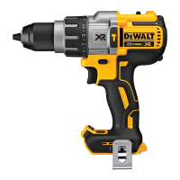
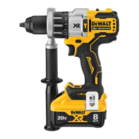
Installing and Removing the Battery Pack
(Fig.E)
NOTE: For best results, make sure your battery pack is
fullycharged.
To install the battery pack
1
into the tool handle, align the
battery pack with the rails inside the tool’s handle and slide it
OPERATION
WARNING: To reduce the risk of serious personal
injury, turn unit off and remove the battery pack
before making any adjustments or removing/
installing attachments or accessories. An
accidental start‑up can causeinjury.
Speed Selection (Fig. A)
The tool features three speed settings for greaterversatility.
NOTE: Do not change speeds when the tool is running.
Always allow the tool to come to a complete stop before
changingspeed.
• To select speed 1 (highest torque setting), turn the tool
off and permit it to stop. Slide the speed selector
8
all
the way forward.
• Speed 2 (middle torque and speed setting) is in the
middle position.
• Speed 3 (highest speed setting) is to therear.
If the tool does not change speeds, confirm that the
speed selector is completely engaged in the forward or
backposition.
If trouble shifting gears persists, depress and release the
trigger switch and try again.
Mode Selection (Fig. A)
The mode selection collar
5
can be used to select
the correct operating mode depending upon the
plannedapplication.
To select, rotate the collar until the desired symbol aligns
with thearrow.
WARNING: When the mode selection collar is in the
drill or hammerdrill positions, the drill will not clutch.
The drill may stall if overloaded, causing a suddentwist.
Symbol Mode
Drilling
1-11 Screwdriving (higher number = greater torque)
Hammerdrilling
the chuck sleeve
7
clockwise with one hand while
holding the tool with the other. When the chuck is nearly
tightened you will hear a clicking sound. After 8-12 clicks
the chuck is securely tightened around the accessory.
Your tool is equipped with an automatic spindle lock
mechanism. This allows you to open and close the chuck
with onehand.
Be sure to tighten chuck with one hand on the chuck sleeve
and one hand holding the tool for maximumtightness.
To release the accessory, repeat steps 1 and 2above.
Installing a Bit or Accessory into a Keyless
Chuck (Fig. D)
WARNING: Do not attempt to tighten drill bits (or
any other accessory) by gripping the front part of the
chuck and turning the tool on. Damage to the chuck
and personal injury may result. Always lock off trigger
switch and disconnect tool from power source when
changingacces sories.
WARNING: Always ensure the bit is secure before
starting the tool. A loose bit may eject from tool
causing possible personalinjury.
To insert a drill bit or other accessory, follow thesesteps.
1. Turn tool off and remove batterypack.
2. Grasp the black sleeve of the chuck with one hand
and use the other hand to secure the tool. Rotate the
sleeve counterclockwise far enough to accept the
desiredaccessory.
3. Insert the accessory about 3/4" (19 mm) into the
chuck
6
and tighten securely by grasping and rotating
Side Handle (Fig.A)
WARNING: To reduce the risk of personal injury,
ALWAYS operate the tool with the side handle properly
installed. Failure to do so may result in the side handle
slipping during tool operation and subsequent loss of
control. Hold tool with both hands to maximizecontrol.
Side handle
14
clamps to the front of the gear case and may
be rotated 360° to permit right- or left-hand use. Side handle
must be tightened sufficiently to resist the twisting action
of the tool if the accessory binds or stalls. Be sure to grip the
side handle at the far end to control the tool during astall.
ASSEMBLY AND ADJUSTMENTS
WARNING: To reduce the risk of serious personal
injury, turn unit off and remove the battery pack
before making any adjustments or removing/
installing attachments or accessories. An
accidental start‑up can causeinjury.
Wall Mounting
Some
chargers are designed to be wall mountable
or to sit upright on a table or work surface. If wall mounting,
locate the charger within reach of an electrical outlet, and
away from a corner or other obstructions which may impede
air flow. Use the back of the charger as a template for the
location of the mounting screws on the wall. Mount the
charger securely using drywall screws (purchased separately)
at least 1” (25.4mm) long, with a screw head diameter of
0.28–0.35” (7–9mm), screwed into wood to an optimal
depth leaving approximately 7/32” (5.5 mm) of the screw
exposed. Align the slots on the back of the charger with the
exposed screws and fully engage them in theslots.
SAVE THESE INSTRUCTIONS FOR
FUTURE USE
may be removed from the exterior of the charger using
a cloth or soft non‑metallic brush. Do not use water or
any cleaningsolutions.

 Loading...