10
ENGLISH
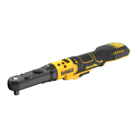
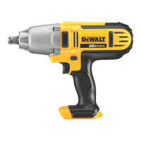
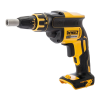
Usage (Fig.A, C)
WARNING: To reduce the risk of serious personal
injury, turn unit off and remove the battery pack
before making any adjustments or removing/
installing attachments or accessories. An accidental
start‑up can causeinjury.
WARNING: The ratchet may stall if overloaded causing
a sudden twist. Always expect the tool to twist. Grip the
ratchet firmly to control the twisting action and avoid
possible personalinjury.
CAUTION: Ensure fastener and/or system will withstand
the level of torque generated by the tool. Excessive torque
may cause breakage and possible personalinjury.
Cat # RPM Ft.-Lbs. Nm
DCF503 0–250 0–60 0–81.35
DCF503E 0–250 0–60 0–81.35
DCF504 0–250 0–40 0–54.23
1. Install appropriate accessory onto the anvil
2
.
2. Place the accessory on the fastenerhead.
3. Consider the intended operation and select either forward
or reverserotation.
4. Press variable speed trigger switch
1
to start operation.
5. Release variable speed trigger switch
1
to stopoperation.
6. If the ratchet stalls, the tool is overloaded or is being
improperly used. Release the variable speed trigger
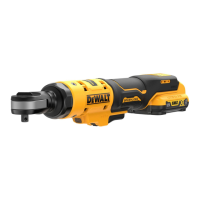
Worklight (Fig.A)
There is a worklight
7
located on the foot of the tool. The
worklight is activated when the trigger switch is depressed.
When the trigger is released, the worklight will stay illuminated
for up to 20seconds.
NOTE: The worklight is for lighting the immediate work surface
and is not intended to be used as aflashlight.
Lock-off Button (Fig.A)
To lock the tool, slide the lock‑off button
8
to the locked
position. When the lock‑off button is in the locked position, the
tool is locked and the trigger switch
1
cannot bepulled.
variable speed trigger
1
. The farther the trigger is depressed,
the higher the speed of the tool. The anvil will stop as soon as
the trigger switch is fullyreleased.
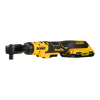
Forward/Reverse Dial (Fig.E)
A forward/reverse control dial
3
determines the rotational
direction of thetool.
• To select forward rotation (clockwise), release the trigger
and rotate the forward/reverse dial
3
on the head of
thetool in a counterclockwisedirection.
• To select reverse rotation (counterclockwise), release the
trigger and rotate the forward/reverse dial
3
on the head of
thetool in a clockwisedirection.
NOTE: The first time the tool is run after changing the direction
of rotation, you may hear a click on start up. This is normal and
does not indicate aproblem.
Variable Speed Trigger (Fig.A)
The tool is turned on and off by pulling and releasing the
Proper Hand Position (Fig.D)
WARNING: To reduce the risk of serious personal injury,
ALWAYS use proper hand position as shown.
WARNING: To reduce the risk of serious personal injury,
ALWAYS hold securely in anticipation of a suddenreaction.
WARNING: Ratchet may stall (if overloaded or improperly
used) causing a twist. Always expect the stall. Grip the
ratchet firmly to control the twisting action and prevent
loss of control which could cause personalinjury.
Proper hand position requires one hand on the main handle
7
as
shown to control the twisting action of theratchet.
OPERATION
Instructions for Use
WARNING: Always observe the safety instructions and
applicableregulations.
WARNING: To reduce the risk of serious personal
injury, turn tool off and disconnect battery pack
before making any adjustments or removing/
installing attachments or accessories. An accidental
start‑up can causeinjury.
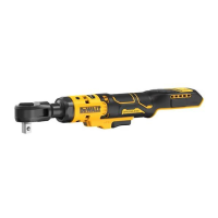
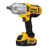
Anvil (Fig.D)
CAUTION: Inspect anvil prior to use. Missing or damaged
items should be replaced beforeuse.
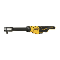
NOTE: The DCF503 ships with 1/2" square anvil. The DCF504
ships with 3/8" squareanvil.
To install an accessory on the anvil, align the accessory with
the anvil
2
. Press the accessory onto the anvil
2
.
To remove an accessory, pull the accessory off the anvil
2
.
2. Slide it into the handle until the battery pack is firmly seated
in the tool and ensure that you hear the lock snap intoplace.
To Remove the Battery Pack from the Tool
1. Press the battery release button
4
and firmly pull the
battery pack out of the toolhandle.
2. Insert battery pack into the charger as described in the
charger section of thismanual.
Fuel Gauge Battery Packs (Fig.B)
Some DeWALT battery packs include a fuel gauge which
consists of three green LED lights that indicate the level of
charge remaining in the batterypack.
To actuate the fuel gauge, press and hold the fuel gauge
button
10
. A combination of the three green LED lights will
illuminate designating the level of charge left. When the level
of charge in the battery is below the usable limit, the fuel gauge
will not illuminate and the battery will need to berecharged.
NOTE: The fuel gauge is only an indication of the charge left on
the battery pack. It does not indicate tool functionality and is
subject to variation based on product components, temperature
and end‑userapplication.