28
ENGLISH
Package Contents
The package contains:
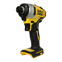
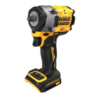
1 Impact driver
1 Charger
1 Magnetic bit holder (included with some models)
1 Belt hook (included with some models)
1 Kitbox (included with some models)
1 Li-Ion battery pack (C1, D1, L1, M1, P1, S1, T1, X1 models)
2 Li-Ion battery packs (C2, D2, L2, M2, P2, S2, T2, X2 models)
3 Li-Ion battery packs (C3, D3, L3, M3, P3, S3, T3, X3 models)
1 Instruction manual
• Check for damage to the tool, parts or accessories which may
have occurred duringtransport.
• Take the time to thoroughly read and understand this manual
prior tooperation.
Markings on Tool
The following pictograms are shown on the tool:
Read instruction manual beforeuse.
Wear earprotection.
Wear eyeprotection.
Visible radiation. Do not stare intolight.
Date Code Position (Fig. A)
The date code
12
, which also includes the year of manufacture,
is printed into thehousing.
Example:
2018 XX XX
Year of Manufacture
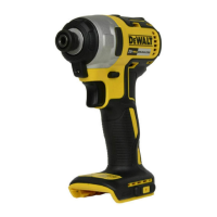
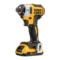
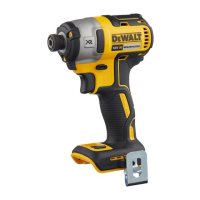
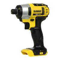
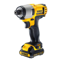
Description (Fig. A)
WARNING: Never modify the power tool or any part of it.
Damage or personal injury couldresult.
1
Trigger switch
2
Forward/reverse button
3
Chuck collar
4
6.35mm hex quick-release chuck
5
Battery release button
6
Battery pack
7
Worklight
8
Belt hook (included with some models)
9
Screw
10
Magnetic bit holder (included with some models)
Intended Use
This impact driver is designed for professional impact
screwdriving applications. The impact function makes this
tool particularly useful for driving fasteners in wood, metal
andconcrete.
DO NOT use under wet conditions or in the presence of
flammable liquids orgases.
This impact driver is a professional powertool.
DO NOT let children come into contact with the tool.
Supervision is required when inexperienced operators use
thistool.
• Young children and the infirm. This appliance is not
intended for use by young children or infirm persons
withoutsupervision.
• This product is not intended for use by persons (including
children) suffering from diminished physical, sensory or
mental abilities; lack of experience, knowledge or skills
unless they are supervised by a person responsible for their
safety. Children should never be left alone with thisproduct.
ASSEMBLY AND ADJUSTMENTS
WARNING: To reduce the risk of serious personal
injury, turn tool off and disconnect battery pack
before making any adjustments or removing/
installing attachments or accessories. An accidental
start-up can causeinjury.
WARNING: Use only
battery packs andchargers.
Inserting and Removing the Battery Pack
from the Tool (Fig. B)
NOTE: Make sure your battery pack
6
is fullycharged.
To Install the Battery Pack into the Tool
Handle
1. Align the battery pack
6
with the rails inside the tool’s
handle (Fig. B).
2. Slide it into the handle until the battery pack is firmly seated
in the tool and ensure that you hear the lock snap intoplace.
To Remove the Battery Pack from the Tool
1. Press the release button
5
and firmly pull the battery pack
out of the toolhandle.
2. Insert battery pack into the charger as described in the
charger section of thismanual.
Fuel Gauge Battery Packs (Fig. B)
Some
battery packs include a fuel gauge which
consists of three green LED lights that indicate the level of
charge remaining in the batterypack.
To actuate the fuel gauge, press and hold the fuel gauge button.
A combination of the three green LED lights will illuminate
designating the level of charge left. When the level of charge
in the battery is below the usable limit, the fuel gauge will not
illuminate and the battery will need to berecharged.
NOTE: The fuel gauge is only an indication of the charge left on
the battery pack. It does not indicate tool functionality and is
subject to variation based on product components, temperature
and end-userapplication.
 Loading...