25
ENGLISH
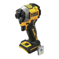
Worklight (Fig.A)
The worklight
7
is activated when the variable speed
trigger switch
3
is depressed, and will automatically turn off
20seconds after the trigger switch is released. If the trigger
switch remains depressed, the worklight will remainon.
NOTE: The worklight is for lighting the immediate work
surface and is not intended to be used as aflashlight.
Variable Speed Trigger and Forward/
Reverse Control Button (Fig.A)
The tool is turned on and off by pulling and releasing the
variable speed trigger switch
3
. The farther the trigger is
depressed, the higher the speed of the tool. Your tool is
equipped with a brake. The chuck will stop as soon as the
trigger switch is fullyreleased.
A forward/reverse control button
4
determines the
rotational direction of the tool and also serves as a
lock-offbutton.
• To select forward rotation (clockwise), release the trigger
and depress the forward/reverse control button on the
right side of thetool.
• To select reverse (counterclockwise), depress the
forward/reverse control button on the left side of
thetool.
NOTE: The center position of the control button locks the
tool in the off position. When changing the position of the
control button, be sure the trigger isreleased.
NOTE: Continuous use in variable speed range is not
recommended. It may damage the switch and should
beavoided.
NOTE: The first time the tool is run after changing the
direction of rotation, you may hear a click on start-up. This is
normal and does not indicate aproblem.
Proper Hand Position (Fig.F)
WARNING: To reduce the risk of serious personal
injury, ALWAYS use proper hand position as shown.
WARNING: To reduce the risk of serious personal
injury, ALWAYS hold securely in anticipation of a
suddenreaction.
Proper hand position requires one hand on the main
handle
11
.
Installing and Removing the Battery Pack
(Fig.E)
WARNING: Ensure the tool/appliance is in the off
position before inserting the batterypack.
NOTE: For best results, make sure your battery pack is
fullycharged.
1. To install the battery pack
1
into the tool handle, align
the battery pack with the rails inside the tool’s handle
and slide it into the handle until the battery pack is firmly
seated in the tool and ensure that it does notdisengage.
2. To remove the battery pack from the tool, press the
battery release button
2
and firmly pull the battery
pack out of the tool handle. Insert it into the charger as
described in the charger section of thismanual.
OPERATION
WARNING: To reduce the risk of serious personal
injury, turn unit off and remove the battery pack
before making any adjustments or removing/
installing attachments or accessories, when
replacing line, or prior to cleaning. An accidental
start-up can causeinjury.
Quick-Release Chuck (Fig.A, D)
WARNING: Use only impact accessories. Non-impact
accessories may break and cause a hazardous
condition. Inspect accessory prior to use to ensure that
it con tains nocracks.
NOTE: The chuck accepts 1/4" (6.35 mm) hex accessories
and 1" (25.4 mm) bit tipsonly.
Place the forward/reverse button
4
in the lock-off
(center) position and remove battery pack
1
before
changingaccessories.
To install an accessory, fully insert the accessory into the
hex quick-release chuck
6
. The accessory is locked into
place.To remove an accessory, pull the chuck collar
5
away from the front of the tool. Remove the accessory from
the quick-release chuck
6
.
ASSEMBLY AND ADJUSTMENTS
WARNING:
To reduce the risk of serious personal
injury, turn unit off and
remove the battery pack
before making any adjustments or removing/
installing attachments or accessories, when
replacing line, or prior to cleaning. An accidental
start-up can causeinjury.
Wall Mounting
Some DeWALT chargers are designed to be wall mountable
or to sit upright on a table or work surface.If wall mounting,
locate the charger within reach of an electrical outlet, and
away from a corner or other obstructions which may impede
air flow. Use the back of the charger as a template for the
location of the mounting screws on the wall. Mount the
charger securely using drywall screws (purchased separately)
at least 1” (25.4mm) long, with a screw head diameter of
0.28–0.35” (7–9mm), screwed into wood to an optimal
depth leaving approximately 7/32” (5.5 mm) of the screw
exposed. Align the slots on the back of the charger with the
exposed screws and fully engage them in theslots.
SAVE THESE INSTRUCTIONS FOR
FUTURE USE
Charger Cleaning Instructions
WARNING: Shock hazard. Disconnect the charger
from the AC outlet before cleaning. Dirt and grease
may be removed from the exterior of the charger using
a cloth or soft non-metallic brush. Do not use water or
any cleaningsolutions.
 Loading...