ENGLISH
11
Fig. D
5
Rotating the Gear Case (Fig. E)
To improve user comfort, the gear case will rotate 90° for
cuttingoperations.
1. Remove the four corner screws attaching the gear case
to motorhousing.
2. Without separating the gear case from motor housing,
rotate the gear case head to desiredposition.
90˚
90˚
Fig. E
NOTE: If the gear case and motor housing become
separated by more than 1/8" (3.17 mm), the tool must
be serviced and re-assembled by a
service
center. Failure to have the tool serviced may motor and
bearingfailure.
3. Reinstall screws to attach the gear case to the motor
housing. Tighten screws to 12.5 in.-lbs. torque.
Overtightening could cause screws tostrip.
Guards
CAUTION: Guards must be used with all grinding
wheels, cutting wheels, sanding flap discs,
wire brushes, and wire wheels. The tool may
be used without a guard only when sanding with
conventional sanding discs. Refer to Figure A to see
guards provided with the unit. Some applications may
require purchasing the correct guard from your local
dealer or authorized servicecenter.
NOTE: Edge grinding and cutting can be performed with
Type 27 wheels designed and specified for this purpose;
6.35 mm thick wheels are designed for surface grinding
while thinner Type 27 wheels need to be examined for
the manufacturer's label to see if they can be used for
surface grinding or only edge grinding/cutting. A Type 1
guard must be used for any wheel where surface grinding
is forbidden. Cutting can also be performed by using a
Type41 wheel and a Type 1guard.
NOTE: See the Accessories Chart to select the proper
guard/accessorycombination.
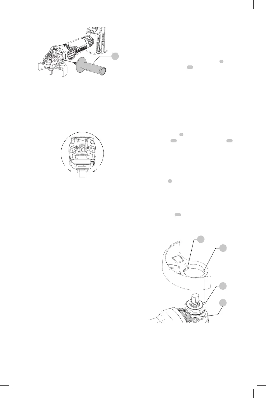
Adjusting and Mounting Guard (Fig. F)
WARNING: To reduce the risk of serious personal
injury, turn tool off and disconnect battery pack
before making any adjustments or removing/
installing attachments or accessories. An
accidental start-up can causeinjury.
CAUTION: BEFORE operating the tool, identify which
guard adjustment option your tool is setto.
Adjustment Options
For guard adjustment, the guard release lever
9
engages
one of the alignment holes
14
on the guard collar using a
ratchetingfeature.
One-touch
TM
: In this position the engaging face is slanted
and will ride over to the next alignment hole when guard
is rotated in a clockwise direction (spindle facing user) but
self-locks in the counter-clockwisedirection.
Mounting Guard (Fig. F)
CAUTION: Prior to mounting guard, ensure the screw,
lever, and spring are fitted correctly before mounting
theguard.
1. With the spindle facing the operator, press and hold the
guard release lever
9
.
2. Align the lugs
12
on the guard with the slots
13
on
the gearcasecover.
3. Push the guard down until the guard lugs engage
and rotate them in the groove on the gear case cover.
Release the guard releaselever.
4. To position the guard, rotate the guard clockwise into
the desired working position. Press and hold the guard
release lever
9
to rotate the guard in the counter-
clockwisedirection.
NOTE: The guard body should be positioned between
the spindle and the operator to provide maximum
operatorprotection.
The guard release lever should snap into one of the
alignment holes
14
on the guard collar. This ensures
that the guard issecure.
5. To remove the guard, follow steps 1–3 of these
instructions inreverse.
9
Fig. F
13
12
14
Flanges and Wheels
CAUTION: Turn unit off and unplug the tool before
making any adjustments or removing or installing
attachments oraccessories.
 Loading...