ENGLISH
12
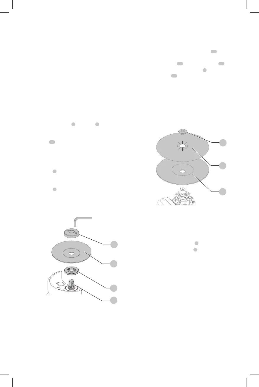
Mounting Non-Hubbed Wheels (Fig. G)
WARNING: Failure to properly seat the flanges and/or
wheel could result in serious injury (or damage to the
tool orwheel).
CAUTION: Included flanges must be used with
depressed center Type 27/42 grinding wheels and
Type1/41 cutting wheels. See the Accessories Chart
for moreinformation.
WARNING: A closed, two-sided cutting wheel guard
is required when using abrasive cutting wheels or
diamond coated cuttingwheels.
WARNING: Use of a damaged flange or guard or fail-
ure to use proper flange and guard can re sult in injury
due to wheel breakage and wheel contact. See the
Accessories Chart for moreinformation.
1. Place the tool on a table, guardup.
2. Install the backing flange
6
on spindle
4
with the
raised center (pilot) facing thewheel. Press the backing
flange intoplace.
3. Place wheel
18
against the backing flange,
centering the wheel on the raised center (pilot) of the
backingflange.
4. While depressing the spindle lock button and with the
hex depressions facing away from the wheel, thread the
locking flange
7
on spindle so that the lugs engage the
two slots in thespindle.
5. While depressing the spindle lock button, tighten the
locking flange
7
by hand or using the wrench supplied.
(Only use a locking flange if it is in perfect condition.)
Refer to Accessory Chart to see flangedetails.
6. To remove the wheel, reverse the aboveprocedure.
Fig. G
7
18
4
6
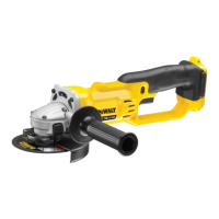
Mounting Sanding Backing Pads
(Fig. A, H)
NOTE: Use of a guard with sanding discs that use backing
pads, often called fiber resin discs, is not required. Since a
guard is not required for these accessories, the guard may or
may not fit correctly ifused.
WARNING: Failure to properly seat the clamp nut
and/or pad could result in serious injury (or damage
to the tool orwheel).
WARNING: Proper guard must be reinstalled for
grinding wheel, cutting wheel, sanding flap disc,
wire brush or wire wheel applications after sanding
applications arecomplete.
1. Place or appropriately thread backing pad
15
on
thespindle.
2. Place the sanding disc
19
on the backing pad
15
.
3. While depressing spindle lock button
3
, thread the
sanding clamp nut
17
on spindle, piloting the raised
hub on the clamp nut into the center of san ding disc
and backingpad.
4. Tighten the clamp nut by hand. Then depress the
spindle lock button while turning the sanding disc until
the sanding disc and clamp nut aresnug.
5. To remove the wheel, grasp and turn the backing
pad and sanding pad while depressing the spindle
lockbutton.
Fig. H
17
19
15
Mounting and Removing Hubbed
Wheels (Fig. A)
Hubbed wheels install directly on the spindle. Thread of
accessory must match thread ofspindle.
1. Remove backing flange by pulling away fromtool.
2. Thread the wheel on the spindle
4
byhand.
3. Depress the spindle lock button
3
and use a wrench to
tighten the hub of thewheel.
4. Reverse the above procedure to remove thewheel.
NOTICE: Failure to properly seat the wheel before
turning the tool on may result in damage to the tool
or thewheel.
Mounting Wire Cup Brushes and
Wire Wheels (Fig. A)
WARNING: Failure to properly seat the brush/wheel
could result in serious injury (or damage to the tool
orwheel).
CAUTION: To reduce the risk of personal injury,
wear work gloves when handling wire brushes
and wheels. They can becomesharp.
CAUTION: To reduce the risk of damage to the
tool, wheel or brush must not touch guard when
mounted or while in use. Undetectable damage
could occur to the accessory, causing wires to
fragment from accessory wheel orcup.
 Loading...