8
DANSK
Brug af forlængerledning
En forlængerledning bør ikke anvendes, undtagen det er
absolut nødvendigt. Brug en godkendt forlængerledning, som
er egnet til din opladers indgangsstrøm (se Tekniske Data).
Den minimale lederstørrelse er 1mm
2
; den maksimale længde
er30m.
Ved brug af en ledningstromle skal ledningen altid
rulles heltud.
Vigtige sikkerhedsinstruktioner for alle
batteriopladere
GEM DISSE INSTRUKTIONER: Denne vejledning indeholder
vigtige sikkerheds‑ og driftsinstruktioner for kompatible
batteriopladere (se
TekniskeData
).
Før du bruger opladeren,
læs alle instruktioner og de sikkerhedsmæssige afmærkninger på
opladeren, batteripakken ogproduktet.
ADVARSEL: Risiko for elektrisk stød. Lad ikke nogen
flydende væsker komme ind i opladeren. Det kan resultere
i et elektriskstød.
ADVARSEL: Vi anbefaler at bruge en fejlstrømsbeskyttelse
med en nominel fejlstrøm på 30mA ellerderunder.
FORSIGTIG: Risiko for brand. For at reducere risikoen
for personskade må du kun oplade DeWALT opladelige
batterier. Andre batterityper kan eksplodere og
forårsagepersonskader.
FORSIGTIG: Børn skal overvåges for at sikre, at de ikke
leger medudstyret.
BEMÆRK: Under bestemte forhold, når opladeren
er tilsluttet til strømforsyningen, kan blotlagte
opladerkontakter blive kortsluttet af fremmede materialer.
Fremmede materialer af en ledende art som for eksempel,
men ikke begrænset til ståluld, aluminumsfolie eller
anden koncentration af metalliske partikler skal holdes på
afstand af opladerens huller. Tag altid stikket til opladeren
ud fra kontakten, når der ikke er indsat en batteripakke.
Tag stikket til opladeren ud før forsøg på at rengøreden.
• Forsøg IKKE at oplade batteripakken med andre
opladere end opladerne i denne vejledning. Opladeren og
batteripakken er specielt designet til at arbejdesammen.
• Disse opladere er ikke beregnet til andre formål end
opladning af DeWALT genopladelige batterier. Alle andre
anvendelser kan medføre risiko for brand, elektrisk stød eller
livsfarlige elektriskestød.
• Udsæt ikke opladeren for regn ellersne.
• Træk i stikket i stedet for ledningen, når opladeren
frakobles. Dette vil reducere risikoen for beskadigelse af
elstikket ogledningen.
• Kontrollér, at ledningen er placeret således, at der ikke
trædes på den, faldes over den, eller den på anden måde
udsættes for skader ellerstress.
• Brug ikke en forlængerledning, med mindre det
er absolut nødvendigt. Anvendelse af en ukorrekt
forlængerledning kan resultere i risiko for brand, elektrisk stød
eller livsfarlige elektriskestød.
• Anbring ikke noget oven på opladeren eller anbring
opladeren på et blødt underlag, der kan blokere
ventilationshullerne og medføre for megen intern
varme. Anbring opladeren på afstand af alle varmekilder.
Opladeren ventileres gennem huller i toppen og bunden
afhuset.
• Brug ikke opladeren med beskadiget ledning eller stik
–få dem udskiftet med detsamme.
• Brug ikke opladeren, hvis den har fået et hårdt slag, er
blevet tabt eller blevet beskadiget på anden vis. Tag den
med til et autoriseretværksted.
• Demontér ikke opladeren, tag den med til et autoriseret
værksted, når service eller reparation er påkrævet. Ukorrekt
genmontering kan medføre risiko for elektrisk stød, livsfarlige
elektriske stød ellerbrand.
• Hvis ledningen beskadiges, skal den omgående udskiftes af
producenten, hans forhandler eller lignende kvalificeret person
for at forebygge enhverrisiko.
• Tag stikket til opladeren ud af kontakten inden forsøg på
rengøring. Dette vil reducere risikoen for elektrisk stød.
Fjernelse af batteripakken vil ikke reducere dennerisiko.
• Forsøg ALDRIG at forbinde to opladere medhinanden.
• Opladeren er udformet til at fungere på en almindelig
230V stikkontakt. Forsøg ikke at bruge den med
en anden strømstyrke. Dette gælder ikke for opladere
tilkøretøjer.
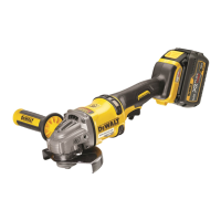
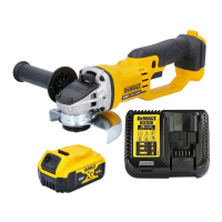
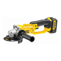
Opladning af et batteri (Fig. B)
1. Tilslut opladeren til en passende stikkontakt før
batteripakken sættesi.
2. Indsæt batteripakken
9
i opladeren og kontrollér, at pakken
sidder godt fast i opladeren. Det røde (opladnings) lys
vil blinke hele tiden og angive, at opladningsprocessen
erstartet.
3. Når opladningen er færdig, vil det blive angivet af den røde
lampe, som vil lyse konstant på ON. Batteripakken er fuldt
opladet og kan nu anvendes eller kan efterlades i opladeren.
For at fjerne batteripakken fra opladeren skal du trykke på
batteriudløserknappen
10
påbatteripakken.
BEMÆRK: For at sikre maksimal ydeevne og levetid for li‑Ion
batteripakker skal batteripakken lades helt op, før den anvendes
førstegang.
Betjening af oplader
Se indikatorerne nedenfor for batteripakkensopladestatus.
Ladeindikatorer
F
Opladning
I
G
Helt opladet
J
H
Varm/kold pakkeforsinkelse*
K
* Det røde lys vil fortsætte med at blinke, men et gult indikatorlys
vil blive tændt under denne handling. Når batteripakken har
opnået en passende temperatur, vil det gule lys blive slukket,
og opladeren vil genoptageopladningsproceduren.
Kompatible oplader(e) vil ikke oplade en defekt batteripakke.
Opladeren vil angive defekt batteri ved at nægte atlyse.
BEMÆRK: Dette kan også betyde et problem medopladeren.
 Loading...