11
ENGLISH
Keep bystandersaway.
Directive 2000/14/EC guaranteed
soundpower.
Date Code Position (Fig.A)
The date code
33
, which also includes the year of manufacture,
is printed into thehousing.
Example:
2017 XX XX
Year of Manufacture
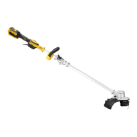
Description (Fig. A)
WARNING: Never modify the power tool or
any part of it. Damage or personal injury couldresult.
1
Variable speed trigger
2
Lock-off lever
3
Handle
4
Speed control switch
5
Auxiliary handle
6
Motor housing
7
Upper trimmer pole
8
Lower trimmer pole
9
Pole bracket
10
Guard
11
Spool housing
12
Battery housing
13
Battery pack
14
Battery release button
Intended Use
This Grass Trimmer is designed for professional
trimmingapplications.
DO NOT use under wet conditions or in the presence of
flammable liquids orgases.
This is not an edger and is not intended to be used foredging.
DO NOT let children come into contact with the tool.
Supervision is required when inexperienced operators use
thistool.
ASSEMBLY AND ADJUSTMENTS
WARNING: To reduce the risk of serious
personal injury, turn tool off and disconnect battery
pack before making any adjustments or removing/
installing attachments or accessories. An accidental
start-up can causeinjury.
WARNING: Use only
battery packs
andchargers.
Inserting and Removing the Battery Pack
from the Tool (Fig. B)
NOTE: Make sure your battery pack
13
is fullycharged.
To Install the Battery Pack into the Tool
1. Align the battery pack
13
with the rails inside the tool
(Fig.B).
2. Slide it into the tool until the battery pack is firmly seated
and ensure that you hear the lock snap intoplace.
To Remove the Battery Pack from the Tool
1. Press the release button
14
and firmly pull the battery pack
out of the toolhandle (Fig.B).
2. Insert battery pack into the charger as described in the
charger section of thismanual.
Fuel Gauge Battery Packs (Fig. B)
Some
battery packs include a fuel gauge which
consists of three green LED lights that indicate the level of
charge remaining in the batterypack.
To actuate the fuel gauge, press and hold the fuel gauge button
15
. A combination of the three green LED lights will illuminate
designating the level of charge left. When the level of charge
in the battery is below the usable limit, the fuel gauge will not
illuminate and the battery will need to berecharged.
NOTE: The fuel gauge is only an indication of the charge left on
the battery pack. It does not indicate tool functionality and is
subject to variation based on product components, temperature
and end-userapplication.
Assembling the Pole (Fig. A, C)
1. To assemble the pole, line up the hole
16
in the lower
trimmer pole
8
with the pin
17
on the pole bracket
9
.
2. Pull the pin out and slide the lower trimmer pole into the
upper trimmer pole
7
as shown in FigureC.
3. Release the pin and ensure it fully engages thehole.
4. Secure the poles by tightening the bracket wingnut
18
.
Attaching Auxiliary Handle (Fig. A, D)
1. Place the auxiliary handle
5
onto the upper trimmer pole
7
above the label placed in the middle of thepole.
2. Slide the bracket
19
of the auxiliary handle into the bottom
of thehandle.
3. Thread the handle bolts
20
through the bracket and into
thehandle.
4. Tighten the handle bolts with the wrench. Ensure the
handle is securelyattached.
If adjustment is necessary, loosen the handle bolts and slide the
auxiliary handle up or down the trimmer pole. Then, retighten
thebolts.
OPERATION
Instructions for Use
WARNING: Always observe the safety
instructions and applicableregulations.